MaixPy #2: Maixduino Pulse Width Modulation (PWM)
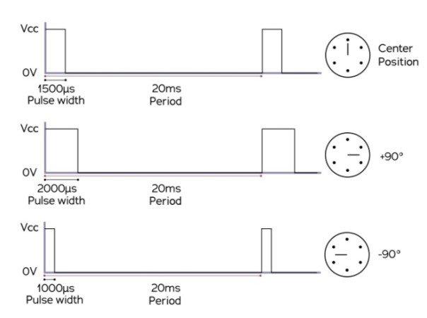
Servo control is a method of controlling servos by sending to the servo a PWM (pulse-width modulation). The parameters for the pulses are the minimal pulse width, the maximal pulse width, and the repetition rate. Given the rotation constraints of the servo, neutral is defined to be the center of rotation. Different servos will have different constraints on their rotation, but the neutral position is always around 1.5 milliseconds (ms) pulse width. [1]
In this tutorial, I am going to talk about the PWM function of the Maixduino and do two experiments. One uses an LED and the other uses a small servo motor.
MaixPy #1: Maixduino First Steps
What Will We Need
![]()
- Maixduino development board: https://s.click.aliexpress.com/e/_DBd6fTF
- LED circuit (Link here for the other Maixduino tutorial)
- Tower Pro SG90 Servo or similar: https://s.click.aliexpress.com/e/_Dmg68rn
- External power supply and some jumper wires
![]()
Maixduino Servo Functions
To use the PWM with the Maixduino, we have to use a Timer and the PWM contructor function. There are 3 timers, and each timer has 4 channels to a maximum of 12 PWM waveforms generated simultaneously.
1#: First, we have to import the PWM and Timer modules:
from machine import Timer,PWM
2# Second, we have to create a Timer and PWM constructors:
tim = Timer(Timer.TIMER0, Timer.CHANNEL0, mode=Timer.MODE_PWM)
ch = PWM(tim, freq=50, duty=50, pin=boad_info.LED_G)
Maixduino PWM LED
The next code creates a pulsating LED brightness. First, it starts with 0% and goes to 100%. After the judgment is made, it starts reducing the intensity from 100% to 0%, and this goes on indefinitely.
We are going to connect an external LED. Simply connect the jumper wires to GND and PIN2. The circuit is here (another Maixduino tutorial).
'''
Experiment Name: PWM LED
Version: v2.0
Date: 2022.03
Changed by: TiagoTech [www.tiagotech.com]
Description: Pulsating LED using PWM
'''

from machine import Timer,PWM
import time
from board import board_info
from fpioa_manager import fm

tim = Timer(Timer.TIMER0, Timer.CHANNEL0, mode=Timer.MODE_PWM)
ch = PWM(tim, freq=500000, duty=50, pin=board_info.PIN2)

duty=0
dir = True

while True:
    if dir:
        duty += 10
    else:
        duty -= 10
    if duty>100:
        duty = 100
        dir = False
    elif duty<0:
        duty = 0
        dir = True
    time.sleep(0.05)
    ch.duty(duty)
Maixduino PWM Servo Calibration
Conneting and controlling a servo motor from the Maixduino Board isn’t straight forward. The servo cannot be powered by the board’s power; it must have its own power source.To efficiently control the servo, we have to make the conversion from Duty Cycle to Degrees. First we have to find the datasheet of a servo and extract its characteristics. In this case, I’m going to use the low-cost SG90 servo, and the characteristics are as follows:
- Weight: 9 g
- Dimensions: 22.2 x 11.8 x 31 mm approx.
- Stall torque: 1.8 kgf·cm
- Operating speed: 0.1 s/60 degree
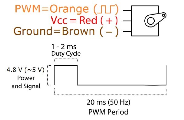
- Operating voltage: 4.8 V (~5V)
- Frequency: 50Hz
- 20 ms PWM Period (1/50Hz)
- Initial position (0º) – 1 ms Pulse
- Center position (90º) – 1.5 ms Pulse
- Final position (180º) – 2 ms Pulse
Duty cycle calculation in (%):
- Initial position: Duty Cycle (0º) = (1/20*100)=2%
- Center position: Duty Cycle(90º) = (1.5/20*100) = 7.5%
- Final position: Duty Cycle(180º) = (2/20*100)=10%
In theory, these should be the Duty Cycle percentages that we should use, but in practice, we have to make adjustments in order for the Servo motor to be positioned correctly.
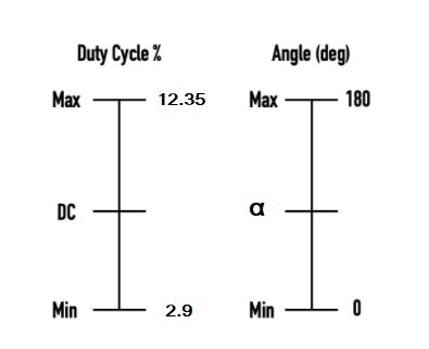
In my case, the final upper and lower limits that I found were: lower = 2.9 and upper = 12.35.
'''
Experiment Name: Servo Calibration
Version: v1.0
Date: 2022.03
Author: TiagoTech [www.tiagotech.com]
Description: Servo Calibration Routine
'''

from machine import Timer,PWM
import time
from board import board_info
from fpioa_manager import fm

tim = Timer(Timer.TIMER0, Timer.CHANNEL0, mode=Timer.MODE_PWM)
PWM_call = PWM(tim, freq=50, duty=50, pin=board_info.PIN2)

while True:
    #PWM_call.duty(2)
    #time.sleep(1)
    PWM_call.duty(2.9)
    time.sleep(1.5)
    #PWM_call.duty(4)
    #time.sleep(1)
    #PWM_call.duty(5)
    #time.sleep(1)
    #PWM_call.duty(6)
    #time.sleep(1)
    PWM_call.duty(7.65)
    time.sleep(1.5)
    #PWM_call.duty(8)
    #time.sleep(1)
    #PWM_call.duty(9)
    #time.sleep(1)
    #PWM_call.duty(10)
    #time.sleep(1)
    #PWM_call.duty(11)
    #time.sleep(1)
    PWM_call.duty(12.35)
    time.sleep(1.5)
    #PWM_call.duty(13)
    #time.sleep(1)
Maixduino PWM Servo Control
Now, it is easier to talk with the servo in Angles instead of Duty Cycle, so we have to make a conversion. We have to use the ranges that we already know; Duty Cycle and Angles.
From my experiment, I found out that the first range is (2.9–12.35) for the Duty Cycle and (0-180º) for the angle range. Next, we are ready to do the mapping:
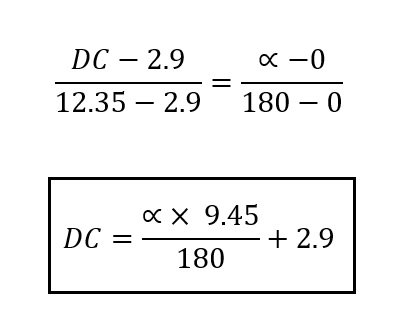
Now that we have the formula, we can make adjustments to the code. We will create a function that will receive two arguments: Angle and Servo, and this will make the conversion from Duty Cycle to Angles.
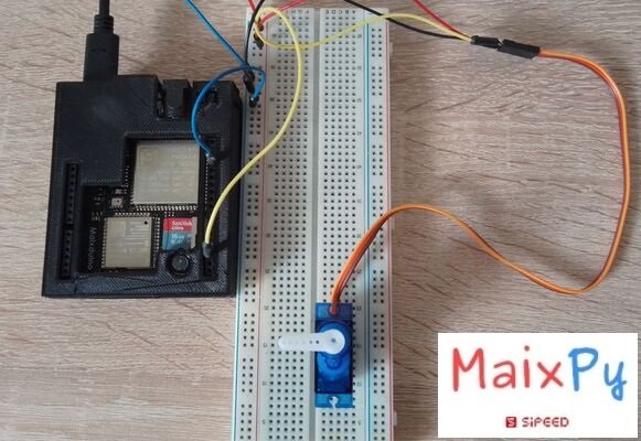
The circuit connections are simple. The important bit is to make sure not to power the Servo from the MaixDuino Pins. These things are Chinese, and the voltage for most of the pins is 3.3V, so we should only use the pins to control the Servo motor (orange wire). Oh, and the ground wires should all be connected (external power supply/Maixduino).
The circuit goes as follows:

The final code:
'''
Experiment Name: Servo Control
Version: v2.0
Date: 2022.03
Author: 01Studio [www.01Studio.org]
Changed by: TiagoTech [www.tiagotech.com]
Description: Control the servo to rotate to different angles through programming
'''

from  machine  import  Timer , PWM
from board import board_info
from fpioa_manager import fm
import  time

#PWM is configured through the timer and connected to the IO21 pin (Pin2 Maixduino Board)
tim  =  Timer ( Timer . TIMER0 , Timer . CHANNEL0 , mode = Timer . MODE_PWM )
S1 = PWM(tim, freq=50, duty=0, pin=board_info.PIN2)

def  Servo ( servo , angle ):
    S1.duty(((angle*9.45)/180)+2.95)

while True:
    #180 degrees
    Servo ( S1 , 180 )
    time.sleep(1)
    #135 degree
    Servo ( S1 , 135 )
    time.sleep(1)
    #90 degrees
    Servo ( S1 , 90 )
    time.sleep(1)
    #45 degree
    Servo ( S1 , 45 )
    time.sleep(1)
    #0 degree
    Servo ( S1 , 0 )
    time.sleep(1)