MaixPy #1: Maixduino First Steps
MicroPython is a lean and efficient implementation of the Python 3 programming language. It includes a small subset of the Python standard library and is optimised to run on microcontrollers and in constrained environments.
Micropython makes programming on K210 hardware easier. The code is open source and can be found on GitHub.
After frustrating attempts with the Arduino IDE, I decided to start the Maixduino Series with the MaixPy IDE. The Arduino IDE is very buggy, as if they put a rookie as tech lead and the result was, in my view, an unfinished project. For now, I will leave it alone to marinate.
In these first steps, I will install all the components necessary for the MaixPy IDE to run correctly. By the end of this tutorial, we are going to be able to activate the video feed of the Maixduino and explore the inboard RGB LED with a simple code.
What Will We Need
![]()
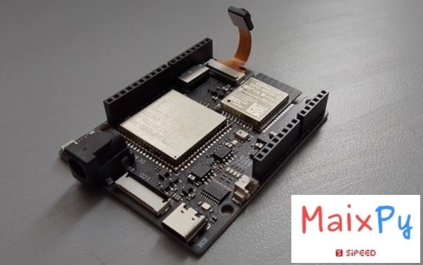
- USB Type-C data cable
- Maixduino development board: https://s.click.aliexpress.com/e/_DBd6fTF
- PC
![]()
- Maiduino Flash Tool: kflash_gui
- MaixPy Firmware
- MaixPy IDE
Step #1: kflash_gui
For newcomers that are starting with the Maixpy installation instead of the Arduino IDE, you have to make sure that the USB driver is installed. The procedure to do this is in this post (First Maixduino Tutorial).
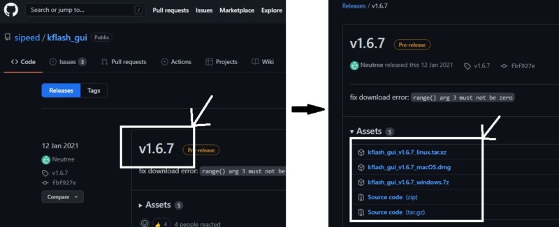
To do the download of the firmware necessary to run the MaixPy IDE, we have to download a program that does that. It is named kflash_gui and is cross-platform and can work under multiple systems (including Windows, Linux, MacOS, and even the Raspberry Pi).
On GitHub, we just need to choose a version of the software and download it for our operating system. Then unzip to a folder, search and double-click on kflash_gui.exe to run the tool.
The link for the download of the tool is as follows:
Instructions:
Step #2: MaixPy Firmware
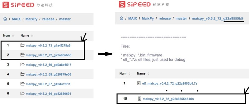
The firmware needed can be found on GitHub. In the middle of a confusion of versions and files with firmware ending in *.bin or *.kfpkg, we can find the one that we want. We can read the firmware readme.txt file to choose the version that we want, but I was lazy and chose the maixpy_*.bin (base one). The version and firmware that I chose (at the time) are as follows, and it worked OK with all my settings:
- maixpy_v0.6.2_72_g22a8555b5_maixpy_v0 (Master directory)
- maixpy_v0.6.2_72_g22a8555b5.bin (Inside Master directory)
Just download the *.Bin file to a place in your computer. The link to the Master directory is as follows:
Instructions:
Step #3: Download the MaixPy firmware to the Maixduino
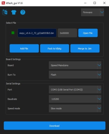
Now we have to open the firmware download tool (kflash_gui.exe) and send the *.Bin file to the Maixduino Board. When using it, please note that the serial port cannot be occupied by other software. Just select the correct development board and serial port number. I reduced the baud rate (115200) and used the low-speed mode to improve the download success rate. It is a little slower, but for me, everything went smoothly.
Instructions:

Step #4: MaixPy IDE Hello World
Now that we’ve downloaded the firmware to the board, we only need to install one more thing: the MaixPy IDE. To do that, we have to go to the Sipeed Download Station (Mega) because the official link wasn’t working and download the version related to your operating system. Then just install the software.
Link_1: MaixPyIDE
Link_2: MaixPyIDE
The benefits of using the MaixPy are as follows:
- Uses
Micropythonscript syntax, so it does not need to be compiled likeClanguage. - Using the
IDEwill facilitate real-time editing of scripts on the computer and upload to the development board, execute scripts directly on the development board, and view camera images on the computer in real time, save files to the development board, etc.
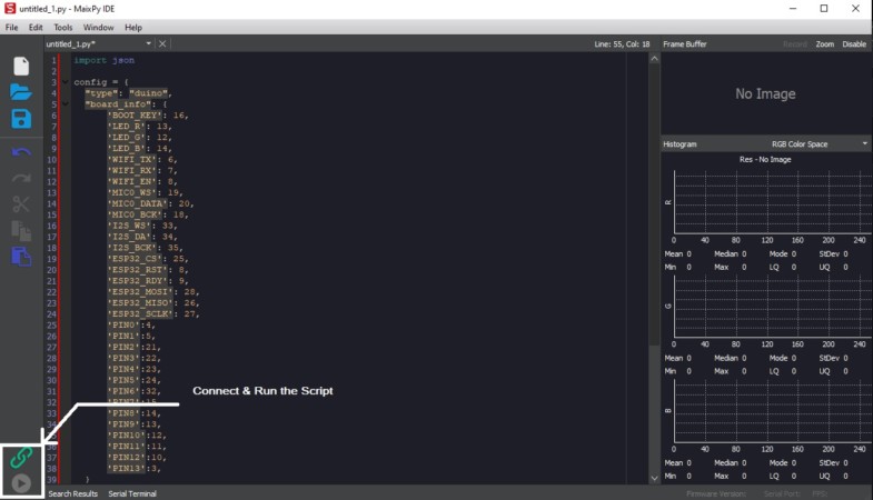
After running MaixPy for the first time, these are the first steps and observations:
- Connect the Maixduino Board to the PC (computer) via usb.
- The helloword_1.py code appears in the coding window
Tool-> Select Board(Tool->Select Board) —> In our case, the Sipeed Maixduno board- Click
connectto connect toMaixPy IDE(Colored Chain Icon) via usb port

- When the connection is successful, the link button will change from green to red
- Below the link button is the run button (Round Icon) that we need to activate, which will execute the
pyfile in the current editing area

If everything goes according to plan, we should be able to see the video feed. This is the final step of the basic configuration.
Extra: Maixduino On board RGB LED
Before we can actualy play with the pins of the MAixduino, we have to upload to the board an configuration script.
-
Board configuration:
We have to copy the python code with the GPIO configuration related to Maixduino, put it in the IDE edit box and run it to complete the import of the “your hardware” configuration item (config.json), which will be stored on the flash Configuration file.
To save a file in the MaixPy IDE, don´t forget to add the extension (*.py)
This is the link to the code :
Visual Instructions:

After this, the Maixduino board pins information should be already stored on the flash Configuration file (Hardware)
-
RBG LED circuit:
As we all know, lighting an LED requires a power supply, a resistor, and an LED bulb,
There are three LEDs on the Maix Dock development board, the wiring is as follows:
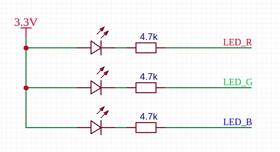
For example, we want the red light to light up, that is, the LED connected to LED_R. As you can see in the picture, the anode of the LED has been connected to a 3.3V power supply, so we only need to make LED_R a low-level LED to light up. –> (led_r.value(0))
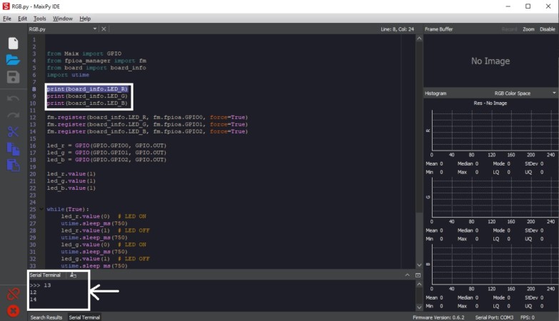
RBG LED Code Explanation:
Set GPIO as input or output mode and Register an IO as a GPIO function::
fm.register(board_info.LED_R, fm.fpioa.GPIO0, force=True)

led_r = GPIO(GPIO.GPIO0, GPIO.OUT)
Read or set GPIO level:
led_r.value(0)
Import the utime library for time related functions:
import utime
Function to add a delay in miliseconds in the code:
utime.sleep_ms(750)
Create a loop (Similar to void loop() in Arduino IDE):
while(True):
Print the information of the pins in the serial monitor:
print(board_info.LED_R)
-
RGB LED in Action:
The files of the project can be downloaded below:
References:
https://wiki.sipeed.com/soft/maixpy/en/