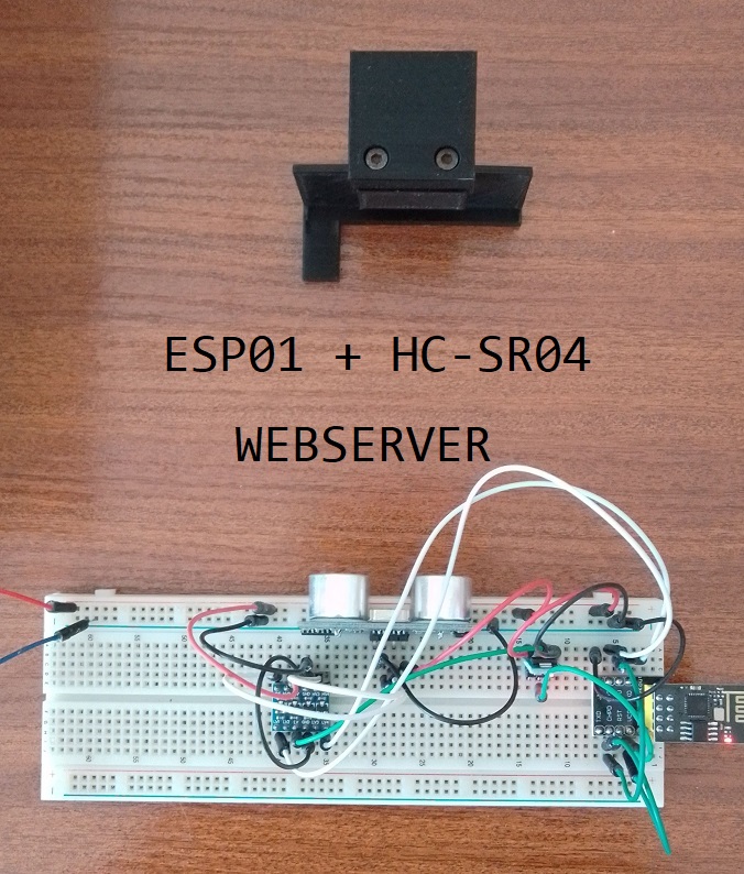
Real-Time Measurement System with ESP01 + HC-SR04
In this blog, we will walk you through the process of creating a real-time distance measurement system using an ESP01 microcontroller and an HC-SR04 ultrasonic distance sensor. This project will allow you to monitor the distance in real-time through a web interface, making it suitable for various applications, such as security systems, home automation, and more.
Components Needed:
- ESP-01 Wi-Fi module (Affiliate) – https://s.click.aliexpress.com/e/_DETsfWR
- Breadboard adapter for ESP-01 (Affiliate) – https://s.click.aliexpress.com/e/_DC3gXdN
- USB ESP-01 Programming Adapter with a CH340G chip (Affiliate) – https://s.click.aliexpress.com/e/_DETsfWR
- HC-SR04 ultrasonic sensor (Affiliate) – https://s.click.aliexpress.com/e/_DBmmmYr
- 5v to 3.3v Converter (Affiliate) – https://s.click.aliexpress.com/e/_DFWA72r
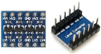
- Logic Converter(Affiliate) – https://s.click.aliexpress.com/e/_Dmx9x5D
- Breadboard and jumper wires (Affiliate) – https://s.click.aliexpress.com/e/_Dl5kuk1
- Power source for ESP01 (e.g., USB cable or external power supply)
- A computer or mobile device to access the distance data via a web interface
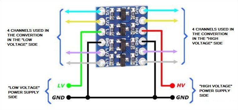
Logic Converter
A logic level converter is used with an ESP01 or other microcontrollers for voltage compatibility when interfacing with devices that use different voltage levels. It ensures proper communication, prevents damage to the microcontroller, and allows for reliable bidirectional communication, making it a crucial component in various electronics projects.
Step-down module
This module allows Esp01 to be powered with 3.3v (it is not tolerant to 5v). Another important feature is that it can supply up to 800mA, which is more than enough to power the Esp01.
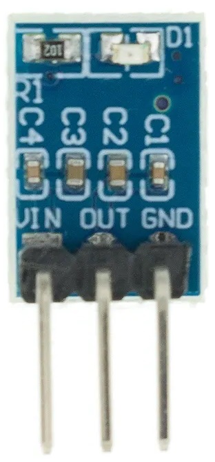
It as 3 pins:
- Vin: In our case 5V from external regulated power suplly
- Out: It will supply 3.3v to the Esp01
- Gnd: Ground pin
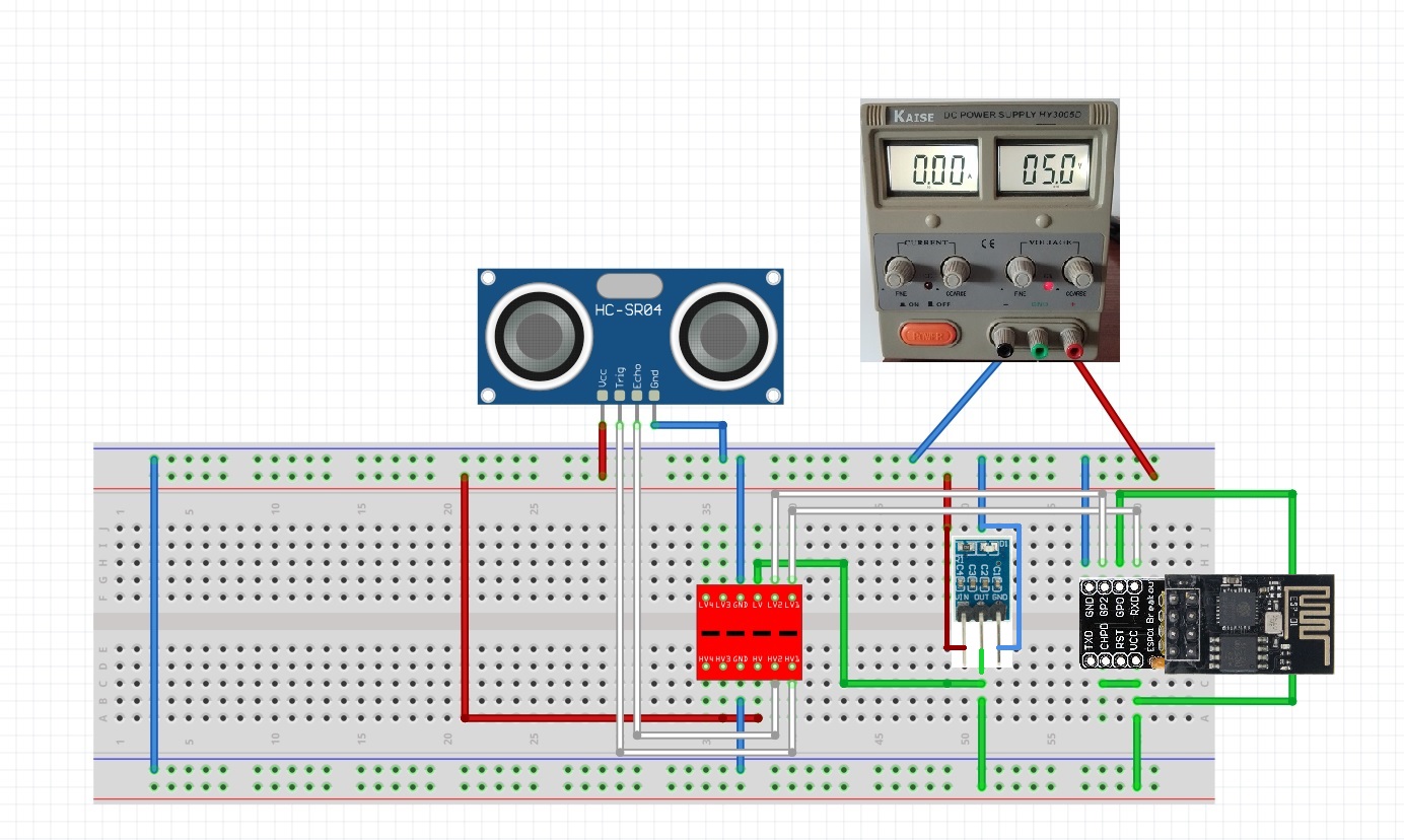
Setting Up Your Hardware:
The HC-SR04 sensor requires two GPIO pins to operate: one for triggering the ultrasonic pulses and another for receiving the echo. In our code, we’ve configured these pins as follows:
- TRIGGER_PIN (Trigger): GPIO3
- ECHO_PIN (Echo): GPIO2

Make sure to connect the HC-SR04 sensor to the ESP01 using the specified GPIO pins. Follow the schematic bellow:
Connecting to Wi-Fi:
To provide real-time updates on the distance measurement, we need the ESP8266 to connect to your Wi-Fi network. Modify the following variables in the code:
ssid: Your Wi-Fi network name.password: Your Wi-Fi password.
If you don´t know your Esp-01 Ip address feel free to check the following post: https://www.edgemicrotech.com/how-to-get-the-ip-address-of-an-esp-01/
The Code:
We’ve written a complete sketch to accomplish this task. The code includes both the server setup and the distance measurement logic.
#include <ESP8266WiFi.h>
#include <ESP8266WebServer.h>

const char* ssid = "YOUR SSID";
const char* password = "YOUR PASSWORD";

const int TRIGGER_PIN = 3; // GPIO3 or any other suitable GPIO pin
const int ECHO_PIN = 2;    // GPIO2 or any other suitable GPIO pin
const int MAX_DISTANCE = 2000; // Maximum distance in millimeters (2 meters)

const int serverPort = 80;
ESP8266WebServer server(serverPort);

void setup() {
  Serial.begin(115200);

  // Connect to Wi-Fi
  WiFi.begin(ssid, password);
  while (WiFi.status() != WL_CONNECTED) {
    delay(1000);
    Serial.println("Connecting to WiFi...");
  }
  Serial.println("Connected to WiFi");
  Serial.print("IP address: ");
  Serial.println(WiFi.localIP());

  // Setup pins for the HC-SR04
  pinMode(TRIGGER_PIN, OUTPUT);
  pinMode(ECHO_PIN, INPUT);

  // Define a route for handling requests
  server.on("/", HTTP_GET, handleRoot);
  server.on("/distance", HTTP_GET, handleDistance); // New route for AJAX request
  server.begin();
}

void loop() {
  server.handleClient();
}

void handleRoot() {
  String html = "<html><body>";
  html += "<h1>HC-SR04 Distance Measurement</h1>";
  html += "<p>Distance: <span id=\"distance\">Updating...</span></p>";
  html += "<script>";
  html += "function updateDistance() {";
  html += "  var xhttp = new XMLHttpRequest();";
  html += "  xhttp.onreadystatechange = function() {";
  html += "    if (this.readyState == 4 && this.status == 200) {";
  html += "      document.getElementById(\"distance\").innerHTML = this.responseText + \" mm\";";
  html += "    }";
  html += "  };";
  html += "  xhttp.open(\"GET\", \"/distance\", true);";
  html += "  xhttp.send();";
  html += "}";
  html += "setInterval(updateDistance, 1000);";
  html += "</script>";
  html += "</body></html>";

  server.send(200, "text/html", html);
}

unsigned int measureDistance() {
  // Trigger the HC-SR04 sensor
  digitalWrite(TRIGGER_PIN, LOW);
  delayMicroseconds(2);
  digitalWrite(TRIGGER_PIN, HIGH);
  delayMicroseconds(10);
  digitalWrite(TRIGGER_PIN, LOW);

  // Measure the echo time
  unsigned long duration = pulseIn(ECHO_PIN, HIGH);

  // Calculate distance in millimeters
  unsigned int distance = duration * 10 / 58; // Speed of sound in air is approximately 343 m/s

  return distance;
}

void handleDistance() {
  unsigned int distance = measureDistance();
  server.send(200, "text/plain", String(distance));
}
This code sets up a web server on the ESP01, which you can access through your web browser. When you visit the server’s IP address, it will display the current distance measured by the HC-SR04 sensor. This measurement is updated every second without the need to manually refresh the page.
Understanding the Code:
- The ESP01 connects to your Wi-Fi network using the provided credentials.
- It sets up two pins for the HC-SR04 sensor: one for triggering the ultrasonic pulses and another for measuring the echo.
- A web server is created, with two routes:
- “/” serves the HTML page that displays the distance, and it uses JavaScript to fetch real-time updates from the server.
- “/distance” provides the current distance value for AJAX requests.
- The
measureDistancefunction is used to trigger the HC-SR04 sensor, calculate the distance, and return it. - The
handleDistancefunction responds to AJAX requests with the current distance measurement.
Understanding the Real Time Update in the Code:
The real-time update in the code is achieved through JavaScript and AJAX (Asynchronous JavaScript and XML). Let me explain how this works step by step:
- HTML Page: In the
handleRootfunction, an HTML page is generated and sent to the client (web browser). The HTML page includes a paragraph element for displaying the distance value. The distance value is enclosed in a<span>element with theidattribute set to “distance,” which allows us to target this element in JavaScript. - JavaScript Function: Within the same HTML page, a
<script>element is used to embed JavaScript code. The JavaScript functionupdateDistanceis defined in this script. Here’s what it does:- It creates an XMLHttpRequest object, which is used to send an HTTP request to the server asynchronously without requiring a full page reload.
- The
onreadystatechangeevent handler is set to respond when the server’s response is received. - Inside the event handler function, when the request is complete (i.e.,
this.readyState == 4and the status is 200), it updates the content of the<span>element with theid“distance” with the new distance value obtained from the server’s response. - The
setIntervalfunction is used to callupdateDistanceevery 1 second (1000 milliseconds), making it update the distance value on the web page periodically.
- AJAX Request: The JavaScript function
updateDistancesends an AJAX GET request to the server at the “/distance” endpoint using the XMLHttpRequest object. This request is made in the background without refreshing the entire web page. - Server Endpoint: The server’s
/distanceendpoint is defined in the code. When the ESP01 receives a GET request at this endpoint, it calls thehandleDistancefunction. handleDistanceFunction: ThehandleDistancefunction is responsible for measuring the current distance using themeasureDistancefunction. It then sends a response back to the client with the distance value as plain text usingserver.send. This response is the real-time distance measurement data requested by the client.- JavaScript Update: When the AJAX request sent by the
updateDistancefunction receives the response from the server (the current distance value), the JavaScript function updates the content of the HTML element with theid“distance” to display the new distance value on the webpage. This process happens every second due to thesetIntervalfunction, creating the illusion of real-time updates.
So, by using AJAX, JavaScript, and periodic updates, the code allows the distance measurement to be displayed and updated in real-time on the webpage without needing to manually refresh the entire page.
Step 5: Connecting the USB to TTL Converter
To put the CH340G adapter in programming mode, follow these steps:
- Before plugging the USB ESP-01 programming adapter into a USB port on your computer, Press and hold the push button switch that you soldered in Step 2 for a few seconds.
- Plug the USB ESP-01 programming adapter into a USB port on your computer with the button pressed.
- Release the button: After a few seconds, release the push button switch. The Esp-01 should be in programming mode, and you can upload code to the ESP-01 module using your preferred development environment.
If having trouble, go to my previous blog post. It explains with images: https://www.edgemicrotech.com/preparing-the-usb-esp-01-programming-adapter-a-step-by-step-guide/
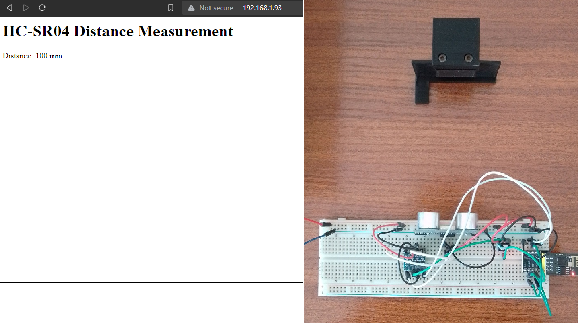
Accessing the Distance Data:
Once you upload the code to your ESP01 and it’s connected to your Wi-Fi network, you can access the distance data by opening a web browser and entering your ESP01’s IP address. The page will show the current distance in real-time, and it will automatically update every second.
Conclusion:
Building a real-time distance measurement system with an ESP01 and an HC-SR04 sensor is a great way to monitor and visualize distances remotely. This project can be extended to include more sensors, integrate with other IoT devices, or trigger actions based on distance values. We hope this blog has been helpful in getting you started with your own distance monitoring project.