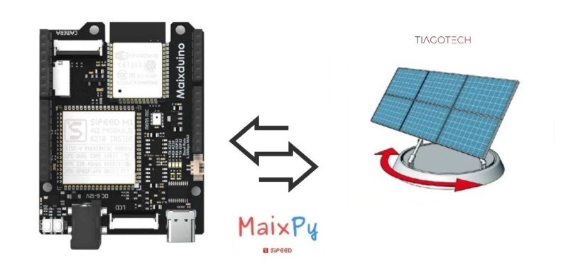
MaixPy #5: Maixduino Solar Tracker (1 Axis) | PWM MicroPython
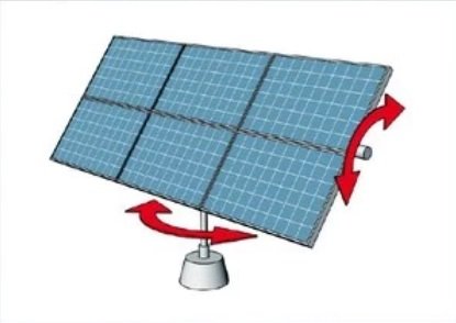
A Solar tracker is a system that positions an object at an angle relative to the Sun. The most common application for solar trackers is the positioning of photovoltaic (PV) panels (solar panels), and it is important that they remain perpendicular to the Sun’s rays . PV solar trackers adjust the direction that a solar panel is facing according to the position of the Sun in the sky. By keeping the panel perpendicular to the Sun, more sunlight strikes the solar panel, less light is reflected, and more energy is absorbed. That energy can then be used to feed the available loads in the system. [1]
The Sun angle changes north to south seasonally and east to west daily. [1]
Solar trackers provide significant advantages for renewable energy. Power output can be increased by 30 to 40% with solar tracking.Key differences between static and solar trackers:
- A static solar panel may have a warranty that spans decades and may require little to no maintenance.
- Solar trackers, on the other hand, have much shorter warranties and require one or more actuators to move the panel. These moving parts increase installation costs and reduce reliability; active tracking systems may also use a small amount of energy (passive systems do not require additional energy). [1]
In this tutorial, I am going to show how to control a servo motor using two LDRs that follow the sun’s light (in this case, a torch light). For that, I will be using the MaixPy IDE.
What Will We Need
![]()
- Maixduino development board: https://s.click.aliexpress.com/e/_DBd6fTF
- Pan/Tilt Set: https://s.click.aliexpress.com/e/_DFDh109
- Breadboard and some jumper wires: https://s.click.aliexpress.com/e/_DB27Kjf
- 2 LDR´s and 4 resistors (10kΩ)
- Extra: 3D printed Solar tracker LDR holder (Thingverse)
![]()
Maixduino Configuration Setup
Introduction
There are four main types of solar trackers:
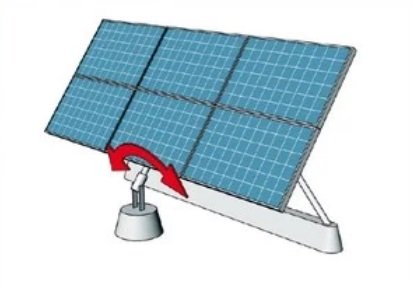
- Horizontal single axis tracking: Rows of modules that track the sun’s elevation.
- Follow the path of the sun as it moves from east to west.
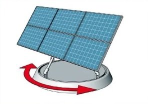
- Azimuth tracker: a single-axis tracker that rotates around a single axis facing east in the mornings and west in the evenings.
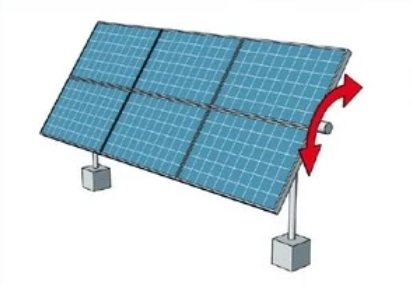
- Dual-axis tracker: in my opinion, the best way to track the sun because it keeps the sun’s rays perpendicular to the surface of the solar panels.
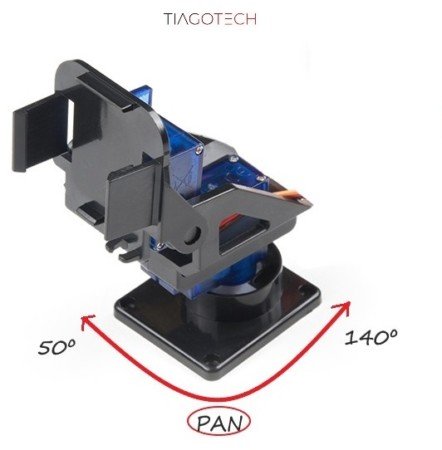
I am going to use the cheap pan/tilt set that i bought from Aliexpress to move only the lower servo (Later down the road, the two of them). The inicial code can be seen in the previous tutorial (MaixPy #4).
In this configuration, i still have to limit the lower servo. To achieve this effect, I limited the rotation to 90º (140-50), starting with 50º and ending with 140º.
In this setup, i used the voltage reference from the 3.3 Volt of the Maixduino board, which is not a good idea. The ADC likes a stable reference voltage, but in this case it worked OK. Maybe in the future, i will dive into making the ADC values more stable.
Single Axis Solar Tracker Configuration Code
The code bits that were added were as follows:
Created a variable called angles to be used in the servo control. In the beginning, it centers the servo.
angles = 90
Created the variable to do the subtraction of the values coming from the LDR’s.
dif_val = 0
Created the variable that establish the error (dead zone) where the servo doesn’t move. It is important because the values coming from the LDRS oscillate a bit. In this case, the error range is [-70 <-> +70] for the dif_val or 2*70 for absdif.
error_val = 70
This is an important step: the extraction of the values from the tuple into the new integer variables ad1 and ad2 . Only this way can we do the arithmetic operations.
ad1, ad2 = wifi.nic.adc((0,1))
dif_val =ad2-ad1
The abs() function gives us the absolute value of the calculated difference.
absdif=abs(dif_val)
With this function, we can see the values of the variables in the serial terminal.
print('ADC0_val:',ad1,'|','ADC1_val:',ad2,'|',...,)
Now we arrive at the important part of the code.
- The jugment if(absdif<error_val) makes the distinction between whether the servo starts moving or not. If the dif_val stays within the error range [-70 +70] or absdif in the 2*70 range, the servo won’t move. If (absdif > error_val), we proceed to the next section using the if-else statement.
- When we enter the if else section of the code, if the value of dif_val >0 the servo moves in one direction because it is incremented by one degree. If the values of (dif_val<0) then the servo changes direction because we decrement by a degree.
if absdif > error_val:
         if dif_val > 0:
               angles=angles+1
         else:
               angles=angles-1
Next, we check the limits of the movement of the servo. In this case, when the servo reaches 160º, the variable angles are updated with the same value (160º or 40º), and the servo stops and does not move forward. The same for the other limit.
if angles > 160:
         angles=160
if angles < 40:
         angles=40
Finally, after all that checking, we update the servo function to move in one direction, the other, or to do nothing (error dead zone or limits).
Servo ( S1 , angles)
Circuit
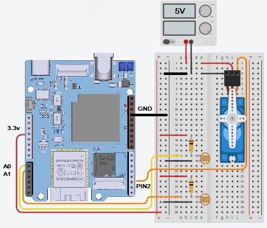
Considerations about the circuit:
- Use an external power supply to power the servos; the Maixduino works at 3.3V and has limited current output
- The ground wires have to be all connected (Maixduino+Power supply)
- Pin2: Pan servo
- I used 2 precison 10kΩ resistors
Final Code
This is the final code. It can also be downloaded at the end of the post (materials section).
'''
Experiment Name: Solar Tracker (1 Axis) Servo Control
Version: v1.0
Date: 2022.04
Author: TiagoTech [www.tiagotech.com]
'''

import time, network, utime
from  machine  import  Timer , PWM
from board import board_info
from Maix import GPIO
from fpioa_manager import fm

#PWM is configured through the timer and connected to the IO21 pin (Pin2 Maixduino Board)
tim  =  Timer ( Timer . TIMER0 , Timer . CHANNEL0 , mode = Timer . MODE_PWM )
S1 = PWM(tim, freq=50, duty=0, pin=board_info.PIN2)

angles = 90 # initial angle

dif_val = 0
error_val = 70 # okok error margin - servo dead range

def  Servo ( servo , angle ):
    S1.duty(((angle*9.45)/180)+2.95)
    time.sleep(0.03)

Servo ( S1 , angles )

class wifi():
    # IO map for ESP32 on Maixduino
    fm.register(8,fm.fpioa.GPIOHS11)#en
    fm.register(9,fm.fpioa.GPIOHS12)#rdy
    fm.register(28,fm.fpioa.SPI1_D0, force=True)#mosi
    fm.register(26,fm.fpioa.SPI1_D1, force=True)#miso
    fm.register(27,fm.fpioa.SPI1_SCLK, force=True)#sclk
    fm.register(25,fm.fpioa.GPIOHS10)#cs
    nic = network.ESP32_SPI(cs=fm.fpioa.GPIOHS10, rst=fm.fpioa.GPIOHS11, rdy=fm.fpioa.GPIOHS12, spi=1)

while True :

    #adc = wifi.nic.adc((0,))
    #adc2 = wifi.nic.adc((1,))
    ad1, ad2 = wifi.nic.adc((0,1)) # Extract values from tuple to int variables ad1 and ad2

    dif_val=ad2-ad1
    absdif=abs(dif_val) # Absolute value convertion

    print('ADC0_val:',ad1, '|' ,'ADC1_val:',ad2, '|','Dif_val:',dif_val,'|','Absdif:',absdif, '|','Error_val:',error_val)

    if absdif > error_val:
        if dif_val > 0:
            angles=angles+1
        else:
            angles=angles-1

    # Limit the travel of the servo (40-160 degrees)
    if angles>160:
        angles=160
    if angles<40:
        angles=40

    Servo ( S1 , angles ) # Give an order to the servo

    utime.sleep_ms(50) # Sofware delay
Maixduino Experiment Materials
References
[1] https://www.britannica.com/technology/solar-tracker
[2] https://wiki.sipeed.com/soft/maixpy/en/
[4] https://sinovoltaics.com/learning-center/csp/single-axis-trackers/