MaixPy #10 : Maixduino 2004 LCD | I2C MicroPython
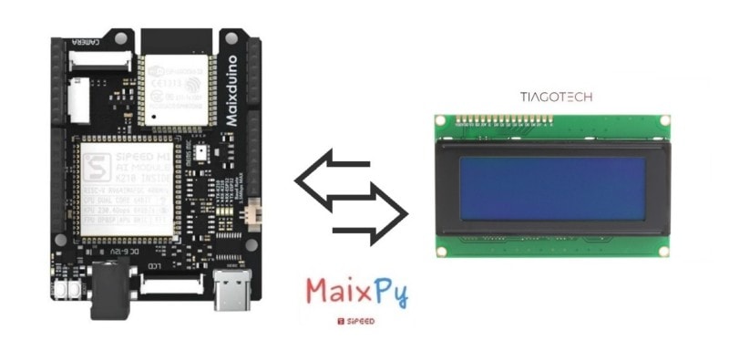
In this tutorial, I am going to interface an 2004 LCD display via I2C with the Maixduino and do some experiments.
The principle of operation is relatively simple at first glance. In this type of screens, there are liquid crystals inside that when they are passed through by a current, the crystal becomes opaque blocking the light (Backlight) that tries to pass. Therefore, the various combinations of specific on and off crystals make it possible for us to visualize on the screen what we want. Although we say that a 20×4 screen has two rows and 16 columns, the display block of basic characters are 5×8 pixels.

Source: https://lastminuteengineers.com/i2c-lcd-arduino-tutorial/
What Will We Need
![]()
- Maixduino development board: https://s.click.aliexpress.com/e/_DBd6fTF
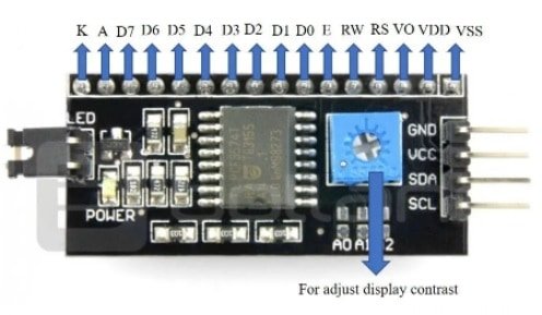
- 2004 LCD display with I2C adaptor: https://s.click.aliexpress.com/e/_DdRrfDP
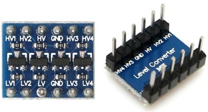
- Logic Level Converter: https://s.click.aliexpress.com/e/_Dd76AfB
![]()
Maixduino I2C Comunication (Simplified)
Introduction
There are other wires on the I2C Bus that constitute the circuit, but the most important ones are:
- SCL: The clock line is responsible for the clock on the bus.
- SDA: The data line is responsible for the transmission of the data.
These wires are connected to all the devices on the bus. In the circuit, there are also two pull-up resistors.
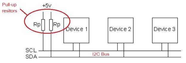
The resistors need to be in the circuit because the transistors are open-drain, which means that when they are activated, they are pulled to the ground (0 volts). The pull-up resistor ensures that the lines remain at the VCC voltage, which is normally 3.3-5 Volt.
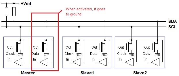
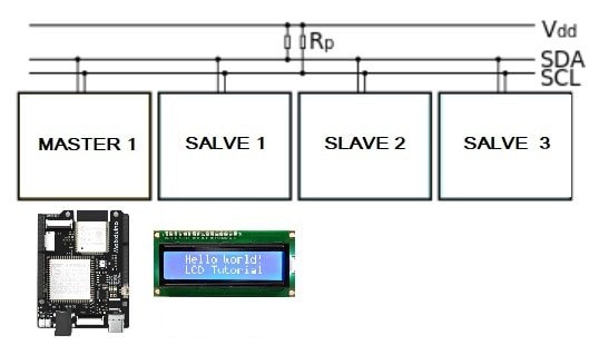
I2C Master / Slave
On the bus, the devices can be either masters or slaves, but the first one (the master) is the one that gives the orders that are given via the SCL clock line. In our case, the Master will be the Maixduino Board, and the Slave, the 2004 Display.
Basic I2C Algorithm
This is a very basic I2C algorithm. There is much more to explore, like the R/W and ACK bits functions. We can write and read from a slave, but the last procedure is a bit more complex (not much). In this case, we only want to send commands to the display, so there is no need to complicate things. To write to a slave device, the algorithm is as follows:
1. Begin by sending a start sequence.This is a unique sequence in which the SDA line is allowed to change to low while the SCL is high.
2. Send the I2C address of the slave with the R/W bit low (even address). Every slave has an address that can be used for communication.
3. Send the internal register number to which you wish to write. Especify were in the memory of the slave (OLED display), we what to write.
4. Send the data byte. Send the info that we want to: display on/off, show text, etc.
5. [Optional: send any additional data bytes]
6. Execute the stop sequence.(Special sequence)

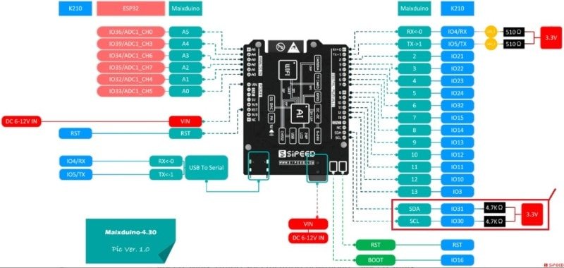
The AI module of the Maixduino board has the ability to implement I2C communication. There are 2 pins available for I2C operations on the board. We can see them highlighted in the schematic below.
Here’s a link to the bigger schematic here (Sipped official site).
Maixduino I2C Pins
The pins used for I2C communication by the Ai Module of the Maixduino board are as follows:
- IO30 I2C1_SCL (AI Module) <–>SCL PIN of the Maixduino Board
- IO31 I2C1_SCA (AI Module) <–>SCA PIN of the Maixduino Board
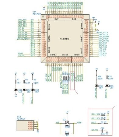
Maixduino original schematic link (Github)
Maixduino I2C Converter Module for LCD
The Maixduno and other microcontrollers have a limited number of digital ports. When connecting an LCD, for example, there will be a few ports left for us to finish our project. With this module, it will only occupy two pins on our Maixduino to use a 16×2, 20×4 LCD or similar.
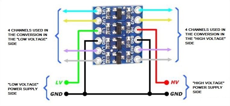
Maixduino Logic Level Converter
It is not good to use voltage levels higher than 3.3 on the Maixduino board pins, so it is necessary (recommended) to use a component that can do this conversion.
The circuit in this tutorial works without the converter with an external power supply at +5V powering the LCD display, but i do not recommend it.
This happens because the LCD needs a supply voltage higher than 3.3 v to work properly. We can see that in the datasheet electrical characteristics of the 2004 LCD:
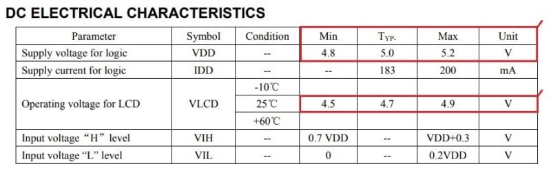
The converter, powered by 5 and 3.3 Volt, allows the conversion of signals to be done either from 5->3.3 Volts or from 3.3->5 Volts.
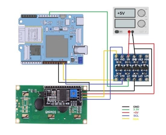
Circuit
It looks like a rats’ nest, I know, but it works
Maixduino I2C Device Search Code
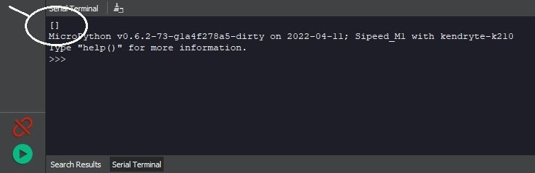
If everything goes according to plan, we need to check the addresses of the devices on the i2c bus. For that, there is a simple code provided by Sipeed.
Double check the pins if the address doesn´t show
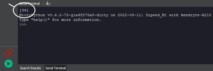
This code is important for us because we need to find out the address of the “slave” to initialize the device in the main 1602 control code. In my case, it gave a [39] that in hexadecimal is [0x27]
from machine import I2C
i2c = I2C(I2C.I2C0, freq=100000, scl=30, sda=31) # hardware i2c
#i2c = I2C(I2C.I2C3, freq=100000, scl=30, sda=31) # software i2c
#[39] --> 0x27 in Hex
devices = i2c.scan()
print(devices)
Effect
With a device plugged in
Without a device being plugged in
Maixduino LCD 2004 Code
I found a Micropython Library related to the 2004 LCD in the GitHub from this guy dork3nergy. It is good but i had to make some changes for it to function with the Maixduino board, the Maixpy funtions are diferent. I made the changes in the lcd_2004 library file that we have to send to the board.
The i2c constructor was diferent so i had to change it from this:
self.i2c=machine.I2C(scl=machine.Pin(SCLPIN), sda=machine.Pin(SDAPIN))
To this:
self.i2c=I2C(I2C.I2C0,mode=I2C.MODE_MASTER,freq=100000, scl=SCLPIN, sda=SDAPIN)
The Maixpy constructor needs more stuff:
- The Id: I2C.I2C0
- The Mode: I2c.MODE_MASTER
- The I2C communication frequency: 100000
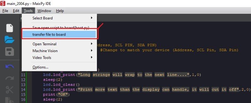
Maixduino 2004_lcd Library Transfer
Now that the changes were made, we can transfer the library to the board to be called when we run the main_2004.py file. This is done by the following comand (the call of the library in the main code):
import lcd_2004
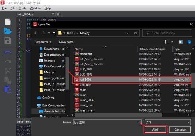
To transfer the libray file, we just need to follow the next steps:
Final main_2004.py code
The main code is pretty strightfoward. we just have to implement the funtion that come with the library. They are as follows:
- lcd_clear() – Clear Screen
- lcd_backlight(boolean) – Set Backlight on or off
- lcd_print(string,line,column) – print string starting on line(1-4) and column(0-19)
- lcd_on() – Turn on display
- lcd_off() – Turn off display
The basic demo code is also good and explains in detail the functions. We just have to make sure that we add the correct information to the constructor:
- The device address: 39 (in my case)
- The SCL Pin Number: 30 (For maixduino)
- The SDA Pin Number: 31 (For Maixduino)
lcd=lcd_2004.lcd(device address,SCL Pin Number,SDA Pin Number)
Besides the demo code, i also created a simple loop with a counter that does, well… nothing good:
count=5

while 1:
    lcd.lcd_print("Counter: {}" .format(count),1,0)
    count=count-1
    utime.sleep_ms(1000)
    if count == 0 :
        lcd.lcd_clear()
        lcd.lcd_print("BOOOM!!",1,0)
        break
Extra: str.format()
Basic syntax for the str.format() method:
"template string {}".format(arguments)
- Inside the template string, we can use
{}which act as placeholders for the arguments. - The arguments are values that will be displayed in the string.
In my example, the argument is the variable count and values will change inside the {}
Problems?
- Check the device address
- Check the SCL and SDA pins of the Maixduino
- Double check all of this in the final code (in bold)
Final Code
import lcd_2004
from time import sleep
import utime

#Usage: lcd_2004(Device Address, SCL PIN, SDA PIN)
lcd=lcd_2004.lcd(39,30,31) #Change to match your device (Address, SCL Pin, SDA Pin)


while(1):
    lcd.lcd_backlight(True)
    lcd.lcd_print("Long strings will wrap to the next line....",1,0)
    sleep(2)
    lcd.lcd_clear()
    lcd.lcd_print("Print more text than the display can handle, it will cut it off",2,0)
    print("OK")
    sleep(2)
    lcd.lcd_clear()
    lcd.lcd_print("Backlight Goes Off",1,0)
    sleep(2)
    lcd.lcd_backlight(False)
    sleep(2)
    lcd.lcd_clear()
    lcd.lcd_print("Backlight Goes On",1,0)
    sleep(2)
    lcd.lcd_backlight(True)
    sleep(2)
    lcd.lcd_clear()
    break

count=5

while 1:
    lcd.lcd_print("Counter: {}" .format(count),1,0)
    count=count-1
    utime.sleep_ms(1000)
    if count == 0 :
        lcd.lcd_clear()
        lcd.lcd_print("BOOOM!!",1,0)
        break
Maixduino Experiment Materials
References
[1] https://www.w3schools.com/python/
[2] https://www.freecodecamp.org/news/python-string-format-python-s-print-format-example/
[3] https://wiki.sipeed.com/soft/maixpy/en/
[4] https://lastminuteengineers.com/i2c-lcd-arduino-tutorial/
[5] https://github.com/dork3nergy/lcd_2004
[7] https://paginas.fe.up.pt/~hsm/docencia/comp/spi-e-i2c/