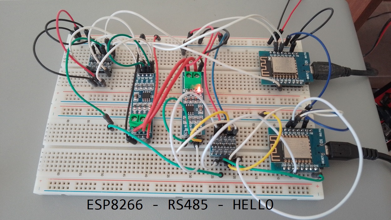
String from an ESP8266 to Another via RS485
In this tutorial, we will learn how to send a string from one ESP8266 to another using an RS485 serial communication module. The ESP8266 is a popular microcontroller board that can be used for various IoT projects, and RS485 is a robust communication protocol often used for longer-distance communication between devices. We will have a sender ESP8266 and a receiver ESP8266 communicating via RS485 using SoftwareSerial.h library.
Components Needed
- 2 x ESP8266 Development Board (such as NodeMCU) (Affiliate) – https://s.click.aliexpress.com/e/_DD3JQhj
- 2 x RS485 Serial Module(Affiliate) – https://s.click.aliexpress.com/e/_DmR4h6b
- 2 x Logic Converter(Affiliate) – https://s.click.aliexpress.com/e/_Dmx9x5D
- Breadboard and jumper wires (Affiliate) – https://s.click.aliexpress.com/e/_Dl5kuk1
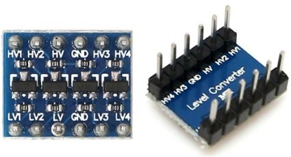
Logic Converter
A logic level converter is used with an ESP8266 or other microcontrollers for voltage compatibility when interfacing with devices that use different voltage levels. It ensures proper communication, prevents damage to the microcontroller, and allows for reliable bidirectional communication, making it a crucial component in various electronics projects.

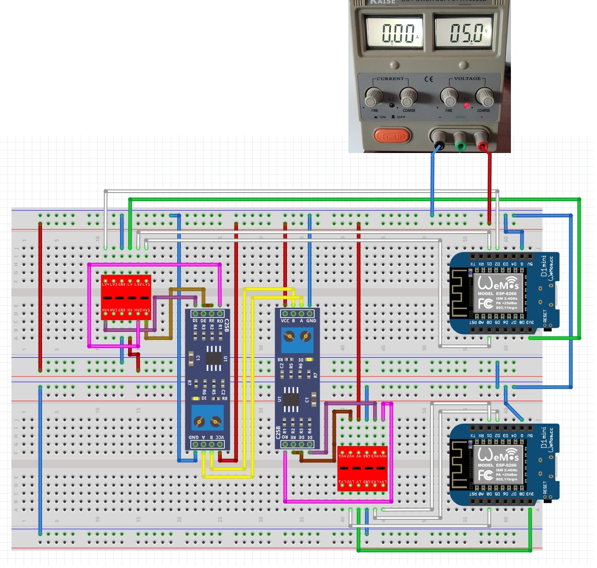
Sender/Receiver Setup Diagram
Wiring
Connect the components for the sender ESP8266 as follows (Better to see the Schematic bellow in case I missed something…):
- Connect the ESP8266’s D2 (TX_PIN) to the RS485 module’s DI (Data In) pin.
- Connect the ESP8266’s D1 (RX_PIN) to the RS485 module’s RO (Receive Out) pin.
- Connect the ESP8266’s D0 (DE/RE_PIN) to the RS485 module’s DE (Data Enable) and RE (Receive Enable) pins.
Library
The SoftwareSerial.h library is included in the Arduino IDE. It is a standard library that comes with the Arduino software, so you don’t need to install it separately. This library allows you to create software-based serial communication ports on your board, which can be useful for various applications, especially when you need to communicate with multiple serial devices using a single hardware serial port. You can include it in your Arduino sketch by using:
#include <SoftwareSerial.h>
Sender Code
Upload the following code to the sender ESP8266:
#include <SoftwareSerial.h>

byte TX_PIN = 4;      // D2 - DI
byte RX_PIN = 5;      // D1 - RO
byte DE_RE_PIN = 16;  // D0 - DE/RE
byte LED_PIN = 2;     // D4

SoftwareSerial Soft_Serial(RX_PIN, TX_PIN);

String message = "Hello, Wemos D1 Mini #2!";

void setup() {
  Serial.begin(115200);
  Soft_Serial.begin(9600);
  pinMode(DE_RE_PIN, OUTPUT);
  digitalWrite(DE_RE_PIN, HIGH);
  pinMode(LED_PIN, OUTPUT);
  digitalWrite(LED_PIN, HIGH);
  Serial.println("Sender Started\n");
}

void loop() {
  Soft_Serial.println(message);
  Serial.println("Message sent: " + message);
  digitalWrite(LED_PIN, LOW);
  delay(10);
  digitalWrite(LED_PIN, HIGH);
  delay(1000);
}
Sender Code Explanation
In the sender code:
TX_PIN(Transmit Pin) is defined as D2, which is connected to the RS485 module’s DI (Data In) pin.RX_PIN(Receive Pin) is defined as D1, which is connected to the RS485 module’s RO (Receive Out) pin.DE_RE_PINis defined as D0, which is connected to the RS485 module’s DE (Data Enable) and RE (Receive Enable) pins.LED_PINis defined as D4, which is connected to an LED for status indication.
In the setup function:
- Serial communication is initialized for debugging purposes.
- The
DE_RE_PIN(D0) is set as an OUTPUT pin, indicating that the ESP8266 is initially in transmit (TX) mode, anddigitalWrite(DE_RE_PIN, HIGH)sets it HIGH, signifying TX mode. LED_PINis configured as an OUTPUT and set HIGH for initial LED state.- A debugging message is printed to the Serial Monitor.
In the loop function:
- The
Soft_Serialobject is used to send the message via RS485 to the receiver. - A debugging message is printed to the Serial Monitor indicating that the message was sent.
- The LED connected to
LED_PINbriefly turns off and then back on as an indicator. - There is a delay of 1 second between sending messages.
Receiver Code
Upload the following code to the receiver ESP8266:
#include <SoftwareSerial.h>

byte TX_PIN = 4;      // D2 - DI
byte RX_PIN = 5;      // D1 - RO
byte DE_RE_PIN = 16;  // D0 - DE/RE
byte LED_PIN = 2;     // D4

SoftwareSerial Soft_Serial(RX_PIN, TX_PIN);

void setup() {
  Serial.begin(115200);
  Soft_Serial.begin(9600);
  pinMode(DE_RE_PIN, OUTPUT);
  digitalWrite(DE_RE_PIN, LOW);
  pinMode(LED_PIN, OUTPUT);
  digitalWrite(LED_PIN, HIGH);
  Serial.println("Receiver Started\n");
}

void loop() {
  if (Soft_Serial.available()) {
    String receivedMessage = Soft_Serial.readStringUntil('\n');
    Serial.println("Received message: " + receivedMessage);
    digitalWrite(LED_PIN, LOW);
    delay(100);
    digitalWrite(LED_PIN, HIGH);
    Soft_Serial.flush();
  }
}
Receiver Code Explanation
In the receiver code:
TX_PINis still defined as D2, which is connected to the RS485 module’s DI (Data In) pin.RX_PINis defined as D1, connected to the RS485 module’s RO (Receive Out) pin.DE_RE_PINis defined as D0, connected to the RS485 module’s DE (Data Enable) and RE (Receive Enable) pins.LED_PINis defined as D4, which is connected to an LED for status indication.
In the setup function of the receiver:
- Serial communication is initialized for debugging.
- The
DE_RE_PIN(D0) is set as an OUTPUT pin, but crucially, it is set LOW initially. This indicates that the ESP8266 is initially in receive (RX) mode. LED_PINis configured as an OUTPUT and set HIGH for initial LED state.- A debugging message is printed to the Serial Monitor.
In the loop function of the receiver:
- It constantly checks if there is data available on the
Soft_Serial(RS485) interface. - If data is available, it reads the received message.
- A debugging message is printed to the Serial Monitor indicating the received message.
- The LED connected to
LED_PINbriefly turns off and then back on as an indicator. - The
Soft_Serialis flushed to clear any remaining data, preparing for the next message.
Why is DE_RE_PIN LOW on the Receiver and HIGH on the Sender?
This configuration follows a common practice in RS485 communication:
- On the sender side,
DE_RE_PINis set to HIGH, indicating that the ESP8266 is in transmit (TX) mode. This enables the RS485 module to send data. - On the receiver side,
DE_RE_PINis set to LOW, indicating that the ESP8266 is in receive (RX) mode. This enables the RS485 module to receive data.
By controlling the DE_RE_PIN in this way, you ensure that only one device at a time is actively transmitting, preventing data collisions on the RS485 bus and ensuring reliable communication between the sender and receiver.
Testing the Communication
- Power up both ESP8266 modules.
- Open the Serial Monitor for both sender and receiver ESP8266s (ensure both are set to 115200 baud).
- You should see the sender ESP8266 sending the message, and the receiver ESP8266 receiving and displaying the message.
Conclusion
In this tutorial, we’ve learned how to send a string from one ESP8266 to another using an RS485 serial communication module. This communication method can be useful in various IoT applications where longer-distance communication is required. You can expand on this project by adding more functionality, such as sending sensor data or controlling devices remotely.