RS485 Communication System with Esp8266
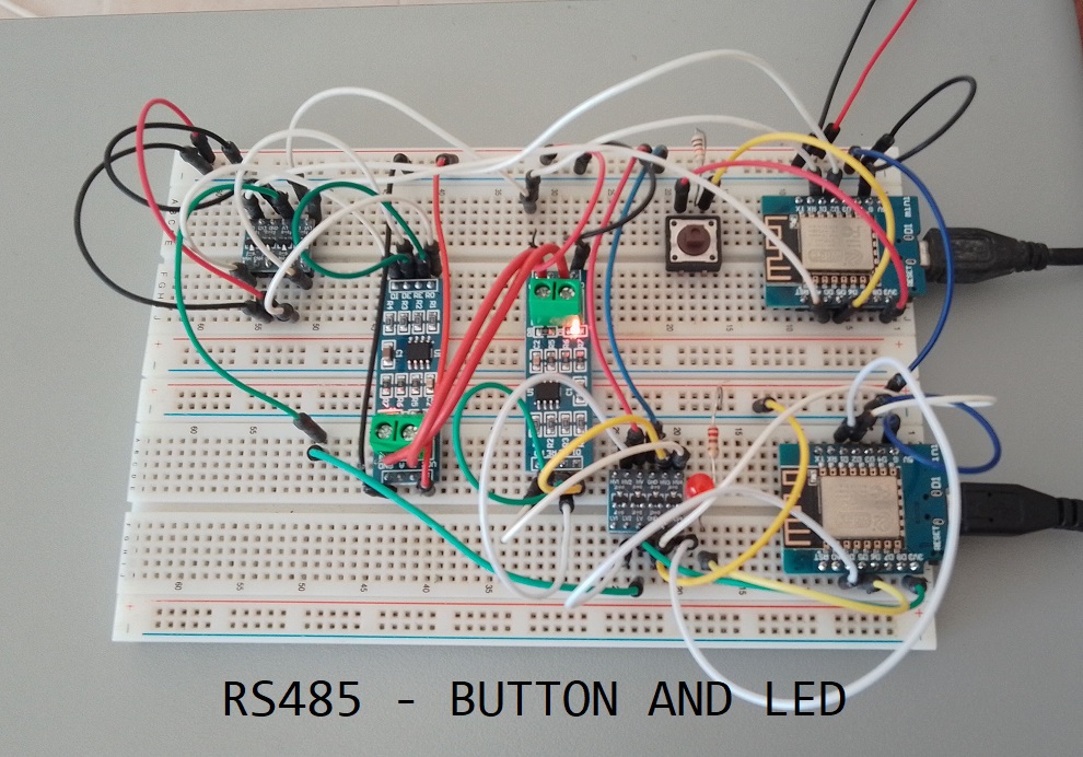
RS485 communication is a widely used standard for serial communication in industrial and automation applications. In this tutorial, we will demonstrate how to establish RS485 communication between two Wemos D1 Mini boards. One board will act as the sender, and the other as the receiver. When a button is pressed on the sender board, it will send a signal to the receiver board, which will then light up an LED. We will provide you with the complete sender and receiver code to make this project work.
Hardware Requirements
- 2 x ESP8266 Development Board (such as NodeMCU) (Affiliate) – https://s.click.aliexpress.com/e/_DD3JQhj
- 2 x RS485 Serial Module(Affiliate) – https://s.click.aliexpress.com/e/_DmR4h6b
- 2 x Logic Converter(Affiliate) – https://s.click.aliexpress.com/e/_Dmx9x5D
- Breadboard and jumper wires (Affiliate) – https://s.click.aliexpress.com/e/_Dl5kuk1
- Push button
- LED and a current-limiting resistor
- USB cables for programming
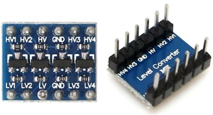
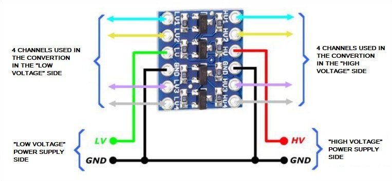
Logic Converter
A logic level converter is used with an ESP8266 or other microcontrollers for voltage compatibility when interfacing with devices that use different voltage levels. It ensures proper communication, prevents damage to the microcontroller, and allows for reliable bidirectional communication, making it a crucial component in various electronics projects.
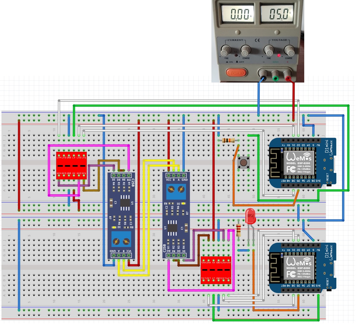
Wiring Section
Connect the components for the sender ESP8266 as follows (Better to see the Schematic bellow in case I missed something…):
- Connect the ESP8266’s D2 (TX_PIN) to the RS485 module’s DI (Data In) pin.
- Connect the ESP8266’s D1 (RX_PIN) to the RS485 module’s RO (Receive Out) pin.
- Connect the ESP8266’s D0 (DE/RE_PIN) to the RS485 module’s DE (Data Enable) and RE (Receive Enable) pins.
- Ensure that both Wemos D1 Mini boards are powered via USB.
- Double check everything, it is easy to make mistakes (i did :))
Sender Code
#include <SoftwareSerial.h>

byte TX_PIN = 4;     // D2 - DI (Transmit Pin)
byte RX_PIN = 5;     // D1 - RO (Receive Pin)
byte DE_RE_PIN = 16; // D0 - DE/RE (Data Enable/Receiver Enable Pin)
byte BUTTON_PIN = 14; // D5 - Button Pin

SoftwareSerial Soft_Serial(RX_PIN, TX_PIN);

bool buttonState = LOW; // Initialize button state as not pressed

void setup() {
  Serial.begin(115200);
  Soft_Serial.begin(9600);
  pinMode(DE_RE_PIN, OUTPUT);
  digitalWrite(DE_RE_PIN, HIGH); // Enable RS485 Transmitter mode
  pinMode(BUTTON_PIN, INPUT_PULLUP); // Configure the button pin as input with pull-up resistor
  Serial.println("\n");
  Serial.println("**** Sender Started ****\n");
}

void loop() {
  int newButtonState = digitalRead(BUTTON_PIN);

  if (newButtonState != buttonState) { // If the button state changes
    if (newButtonState == HIGH) { // If the button is pressed
      Soft_Serial.println("ButtonPressed"); // Send the button press signal
      Serial.println("Button pressed.");
    } else {
      Soft_Serial.println("ButtonReleased"); // Send the button release signal
      Serial.println("Button released.");
    }
    buttonState = newButtonState; // Update the button state
  }
}
Explanation of the Sender Code
- We include the SoftwareSerial library to create a secondary software-based serial communication port for RS485.
- We define the pins used for RS485 communication (TX_PIN, RX_PIN) and the Data Enable/Receiver Enable (DE/RE) pin, along with the pin for the push button (BUTTON_PIN).
- Inside the
setup()function, we initialize the serial communication for debugging, configure the DE/RE pin as an output and set it to HIGH (to enable RS485 transmitter mode), and set up the button pin as an input with a pull-up resistor. - In the
loop()function, we continuously monitor the state of the button. When the button state changes (from pressed to released or vice versa), we send a corresponding message (“ButtonPressed” or “ButtonReleased”) via the software serial port.
Receiver Code
#include <SoftwareSerial.h>

byte TX_PIN = 4;     // D2 - DI (Transmit Pin)
byte RX_PIN = 5;     // D1 - RO (Receive Pin)
byte DE_RE_PIN = 16; // D0 - DE/RE (Data Enable/Receiver Enable Pin)
byte LED_PIN = 14;    // D5 - LED Pin

SoftwareSerial Soft_Serial(RX_PIN, TX_PIN);

void setup() {
  Serial.begin(115200);
  Soft_Serial.begin(9600);
  pinMode(DE_RE_PIN, OUTPUT);
  digitalWrite(DE_RE_PIN, LOW); // Enable RS485 Receiver mode
  pinMode(LED_PIN, OUTPUT);
  digitalWrite(LED_PIN, LOW); // Turn off the LED initially
  Serial.println("\n");
  Serial.println("**** Receiver Started ****\n");
}

void loop() {
  if (Soft_Serial.available()) {
    String receivedMessage = Soft_Serial.readStringUntil('\n');

     // Remove leading/trailing whitespaces from the received message
    receivedMessage.trim();

    // Compare the message without leading/trailing whitespaces
    if (receivedMessage.equals("ButtonPressed")) {
      digitalWrite(LED_PIN, HIGH); // Turn on the LED when "ButtonPressed" is received
      Serial.println("Received message: " + receivedMessage + " and LED ON");
    } else if (receivedMessage.equals("ButtonReleased")) {
      digitalWrite(LED_PIN, LOW); // Turn off the LED when "ButtonReleased" is received
      Serial.println("Received message: " + receivedMessage + " and LED OFF");
    } else {
      Serial.println("Unknown message: " + receivedMessage);
    }
  }
}
Explanation of the Receiver Code
- Similar to the sender code, we include the SoftwareSerial library and define the same RS485 communication pins (TX_PIN, RX_PIN) and the DE/RE pin, along with the LED pin (LED_PIN).
- In the
setup()function, we initialize the serial communication for debugging, configure the DE/RE pin as an output, and set it to LOW (to enable RS485 receiver mode). We also set up the LED pin as an output and turn it off initially. - In the
loop()function, we continuously check if there is data available on the software serial port. When data is received, we read it and trim any leading or trailing whitespace. - We then compare the received message with “ButtonPressed” and “ButtonReleased.” Depending on the message, we either turn the LED on or off and print a corresponding message to the serial monitor.
Testing the Communication
- Power up both ESP8266 modules.
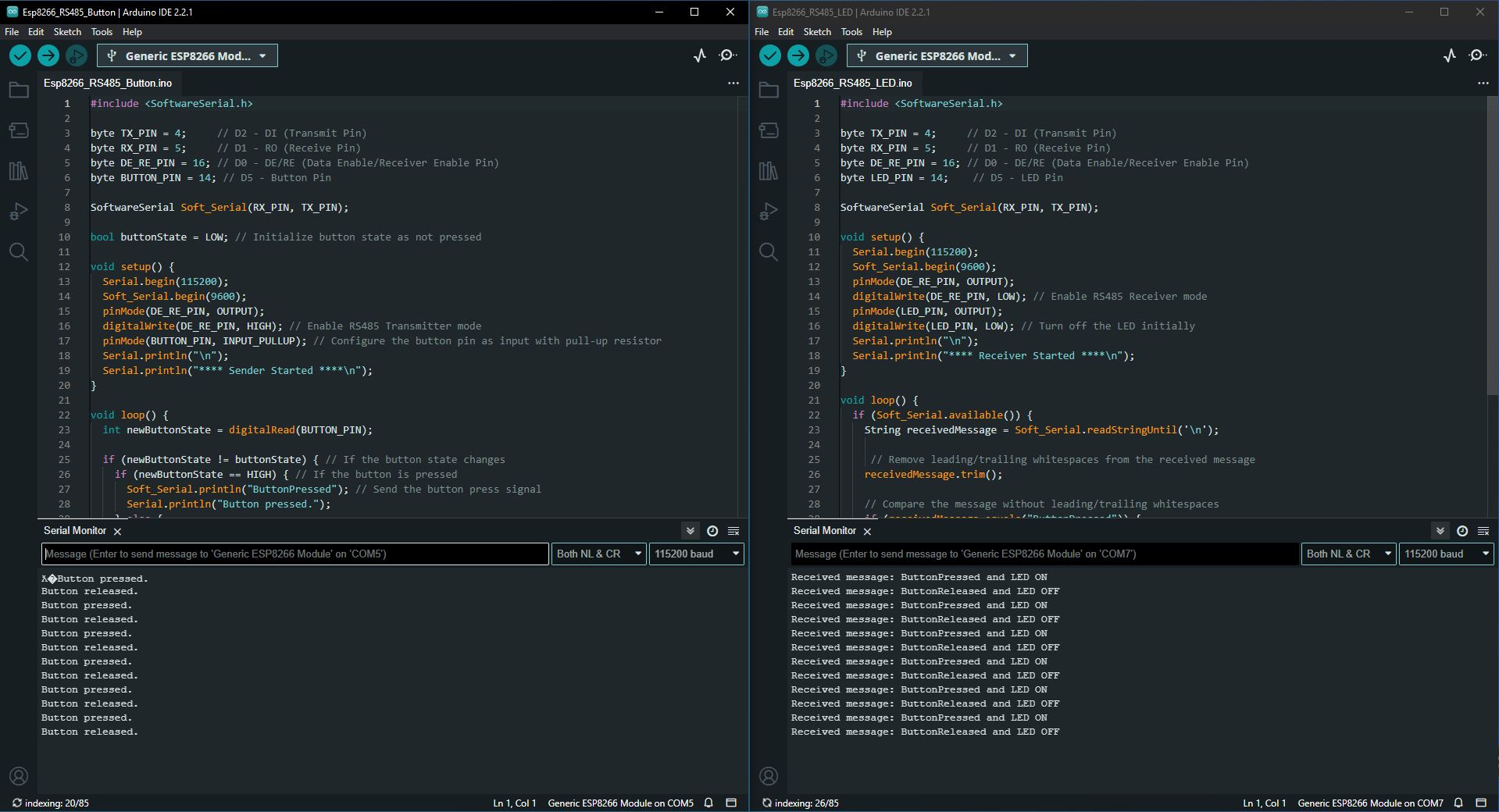
- Open the Serial Monitor for both sender and receiver ESP8266s (ensure both are set to 115200 baud).
- You should see the sender ESP8266 sending the message when we push the button, and the receiver ESP8266 receiving the order to control the LED and displaying the message.
Conclusion
In this tutorial, we’ve demonstrated how to establish RS485 communication between two Wemos D1 Mini boards. The sender board sends a signal when a button is pressed, and the receiver board responds by lighting up an LED. You can expand upon this project by adding more features or using it as a foundation for larger-scale RS485-based projects in industrial and automation settings.