ESP-01 onboard LED from a Button in an ESP8266 via ESP-NOW
ESP-NOW is a powerful communication protocol developed by Espressif that allows for direct communication between ESP devices without the need for Wi-Fi. This makes it an excellent choice for IoT applications where devices need to communicate directly without a central server or router. In this blog post, we will guide you through the process of lighting up the onboard LED of an ESP-01 from a button in an ESP8266 using ESP-NOW.
Materials Needed
- ESP-01 Module (Affiliate) – https://s.click.aliexpress.com/e/_DETsfWR
- Wemos D1 Mini or similar (Affiliate) – https://s.click.aliexpress.com/e/_DD3JQhj
- Breadboard adapter for ESP-01 (Affiliate) – https://s.click.aliexpress.com/e/_DC3gXdN
- USB ESP-01 Programming Adapter with a CH340G chip (Affiliate) – https://s.click.aliexpress.com/e/_DETsfWR
- Breadboard and jumper wires (Affiliate) – https://s.click.aliexpress.com/e/_Dl5kuk1
- Push Button
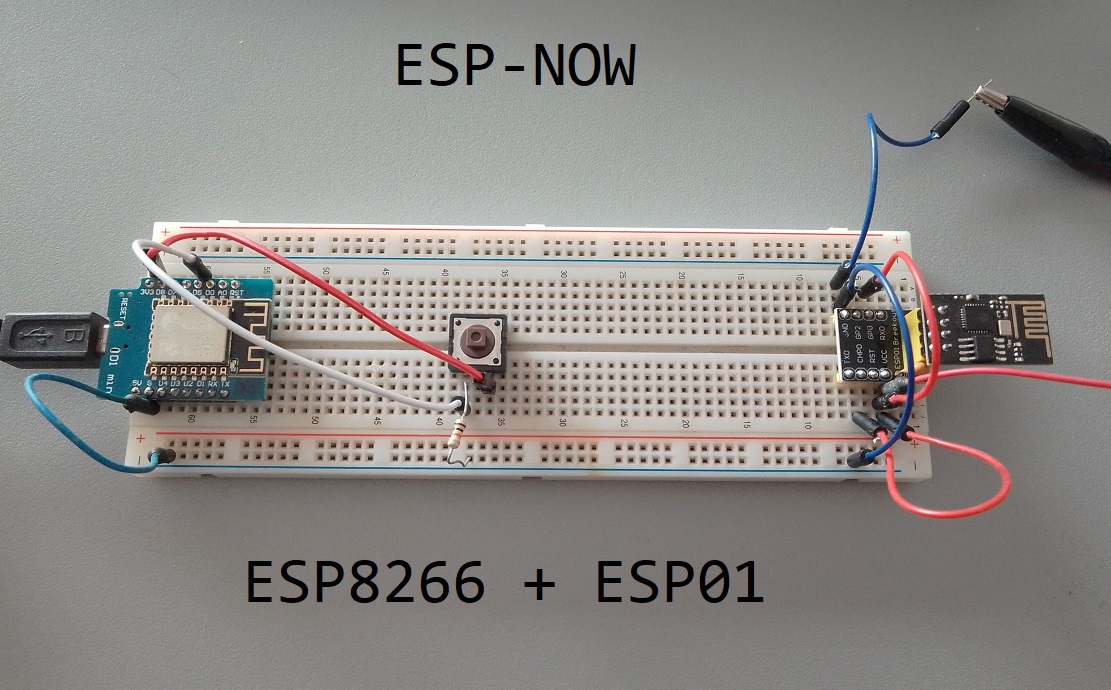
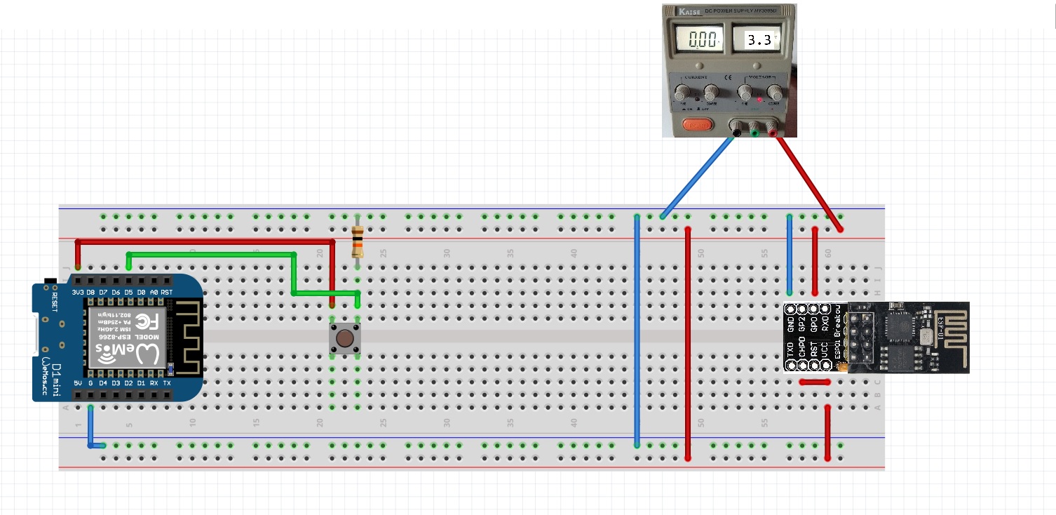
Step 1: Setting Up the Hardware
First, connect the ESP-01 the Wemos D1 Mini to the breadboard. Connect the push button to D5 pin of the Wemos D1 Mini . The other end of the button should be connected to the ground.
Step 2: Installing the ESP8266 Board Package
- Open the Arduino IDE, go to File > Preferences, and add the following URL to the Additional Boards Manager URLs field: http://arduino.esp8266.com/stable/package_esp8266com_index.json.
- Then, go to Tools > Board > Boards Manager, search for ESP8266, and install the package.
Step 3: Programming the D1 Mini (Sender)
We will program the ESP8266 NodeMCU send a signal to the ESP-01 when the button is pressed. To do this, we will use the ESP-NOW protocol. Here is a simple code snippet:
#include <ESP8266WiFi.h>
#include <espnow.h>
uint8_t remoteMac[] = { 0x48, 0x55, 0x19, 0x0C, 0x45, 0x96 };
//48:55:19:0C:45:96
const int buttonPin = D5;
void setup() {
Serial.begin(115200);
pinMode(buttonPin, INPUT);
WiFi.mode(WIFI_STA);
WiFi.disconnect();
esp_now_init();
esp_now_set_self_role(ESP_NOW_ROLE_CONTROLLER);
esp_now_add_peer(remoteMac, ESP_NOW_ROLE_SLAVE, 1, NULL, 0);
}
void loop() {
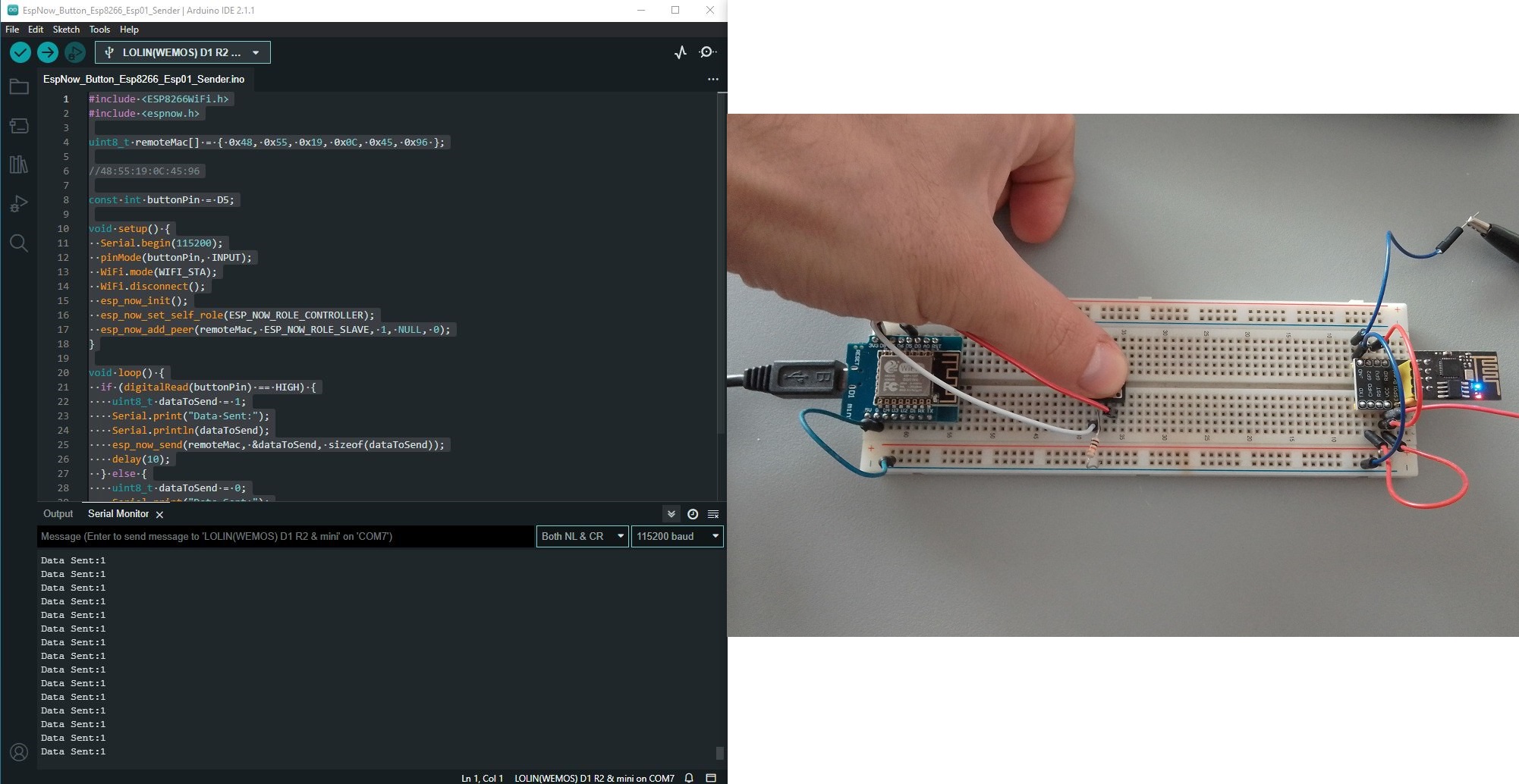
if (digitalRead(buttonPin) == HIGH) {
uint8_t dataToSend = 1;
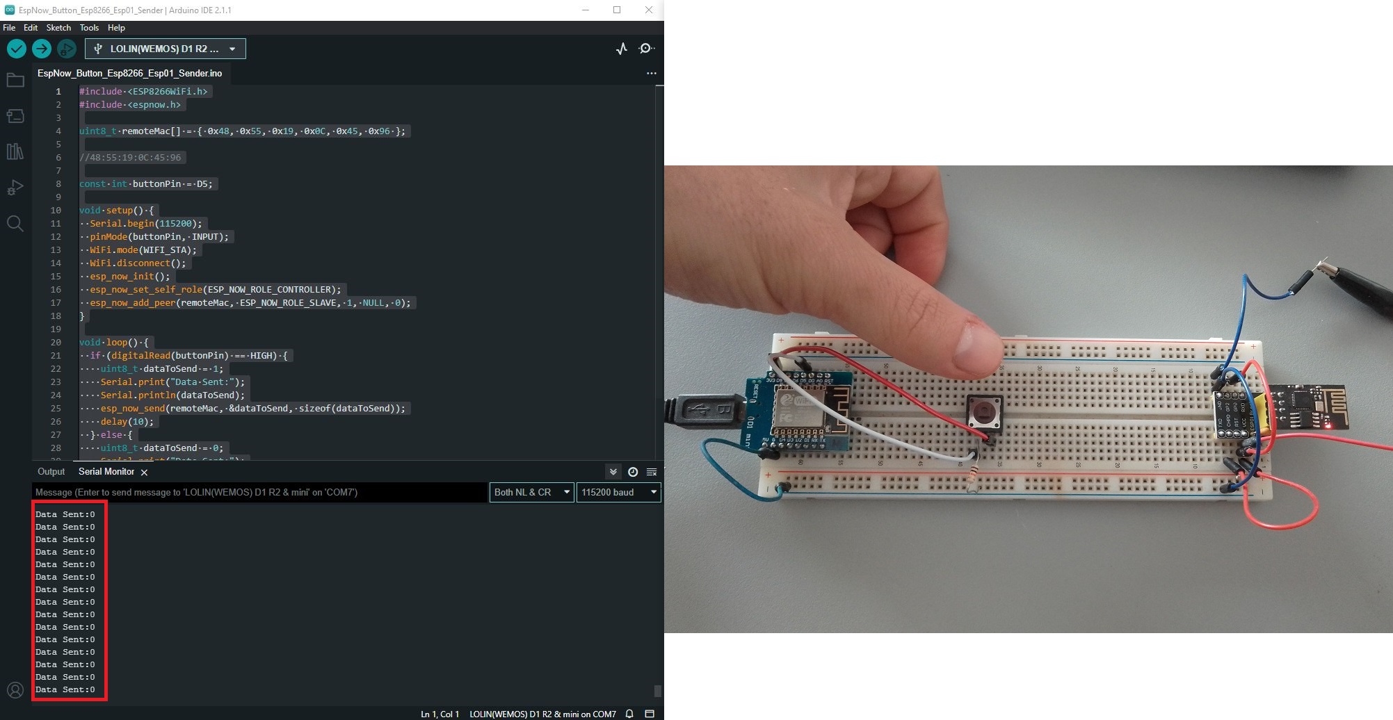
Serial.print("Data Sent:");
Serial.println(dataToSend);
esp_now_send(remoteMac, &dataToSend, sizeof(dataToSend));
delay(10);
} else {
uint8_t dataToSend = 0;
Serial.print("Data Sent:");
Serial.println(dataToSend);
esp_now_send(remoteMac, &dataToSend, sizeof(dataToSend));
delay(10);
}
}
Step 4: Programming the ESP-01 (Receiver)
#include <ESP8266WiFi.h>
#include <espnow.h>


void setup() {
  Serial.begin(115200);
  pinMode(LED_BUILTIN, OUTPUT);
  digitalWrite(LED_BUILTIN, HIGH);
  WiFi.mode(WIFI_STA);
  WiFi.disconnect();
  esp_now_init();
  esp_now_set_self_role(ESP_NOW_ROLE_SLAVE);
  esp_now_register_recv_cb(onDataReceived);
}

void loop() {
  // Nothing to do here, waiting for ESP-NOW messages
}

void onDataReceived(uint8_t *senderMac, uint8_t *data, uint8_t len) {
  if (*data == 1)
  {
    digitalWrite(LED_BUILTIN, LOW);
    Serial.println("LED ON");
  }
  else if(*data == 0)
  {
    digitalWrite(LED_BUILTIN, HIGH);
    Serial.println("LED OFF");
}
}
Step 5: Testing the Setup
Now, upload the respective codes to the ESP8266 NodeMCU and the ESP-01. Press the button on the ESP8266 NodeMCU. The onboard LED of the ESP-01 should light up.