Intelligent Light System with ESP8266
In this era of smart technology, creating your intelligent light system can be an exciting and rewarding DIY project. By combining a KY-019 relay, an ESP8266 module, and a PIR HC-SR501 motion sensor, you can design a system that automatically turns lights on and off based on the presence of motion. In this blog post, we’ll guide you through the process of setting up your own intelligent light system, step by step.
Prerequisites:
- KY-019 Relay Module (Affiliate) – https://s.click.aliexpress.com/e/_DlDFZIX
- ESP8266 Development Board (such as NodeMCU) (Affiliate) – https://s.click.aliexpress.com/e/_DD3JQhj
- HC-SR501 PIR Sensor (Affiliate) – https://s.click.aliexpress.com/e/_DnS5GIF
- Breadboard and jumper wires (Affiliate) – https://s.click.aliexpress.com/e/_Dl5kuk1
- USB cable for ESP8266
- A stable power source (USB charger or power bank)
- Arduino IDE installed on your computer
- Basic understanding of electronics and programming
Understanding the Components
Before we start wiring and coding, let’s briefly understand the components we’re working with:
- KY-019 Relay Module: This module allows you to control high-voltage devices, like lights, using a low-voltage signal from the ESP8266.
- ESP8266: The ESP8266 is a popular microcontroller that provides Wi-Fi connectivity. We’ll use it to interface with the relay and the PIR sensor.
- PIR HC-SR501 Motion Sensor: The Passive Infrared (PIR) sensor can detect motion in its vicinity, which we will use to trigger our intelligent light system.
Warning – High Voltage

Working with Alternating Current is dangerous. Do not attempt to do following wiring schematic if you are not experienced with High Voltage (AC).
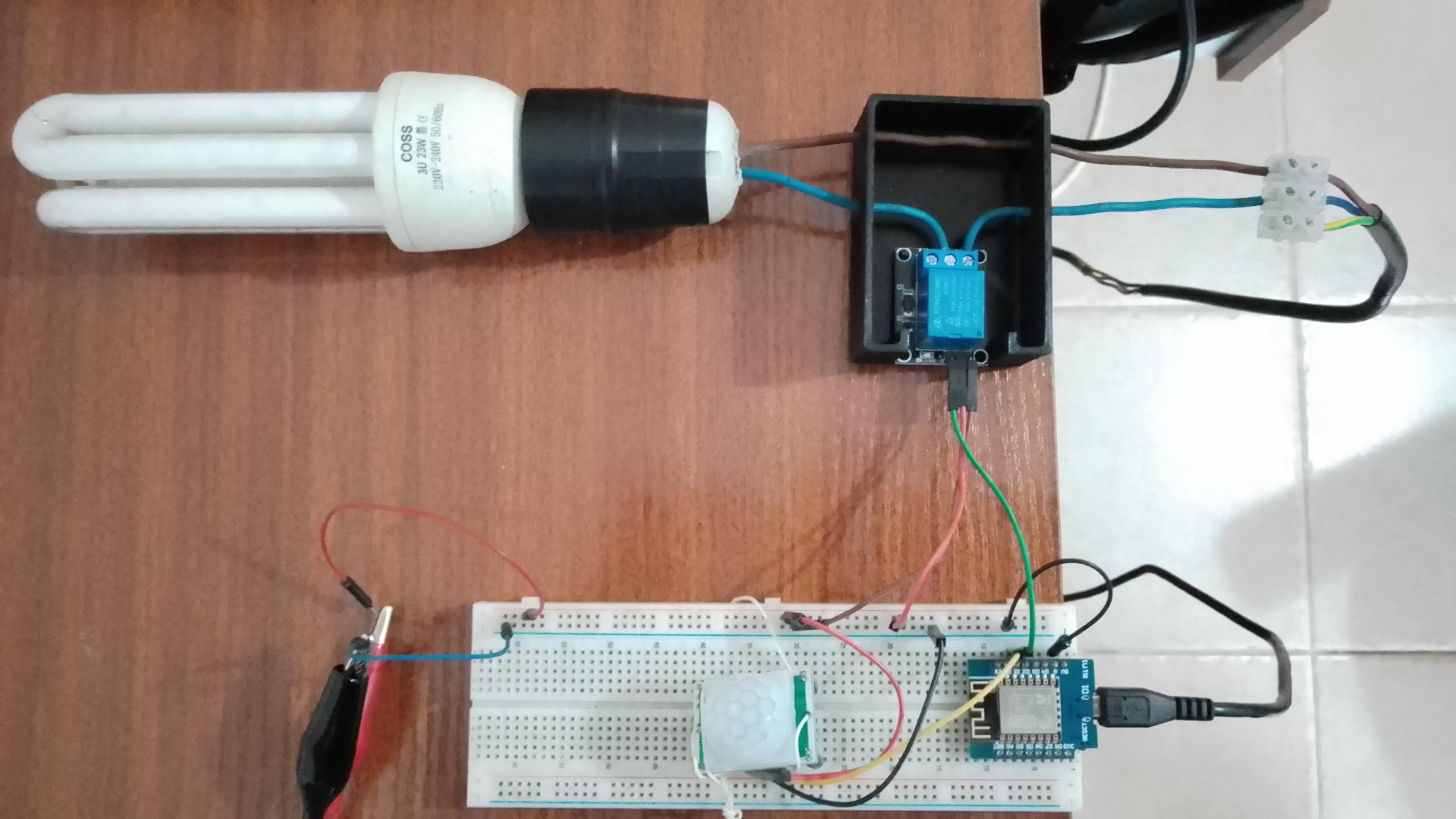
Wiring Connections
- Connect the VCC and GND pins of the PIR HC-SR501 sensor to the 3.3V and GND pins of the ESP8266.
- Connect the OUT pin of the PIR sensor to any available GPIO pin on the ESP8266 (e.g., D2).
- Wire the KY-019 relay module as follows:
- Connect the VCC and GND pins to the 5V and GND pins on the ESP8266.
- Connect the IN pin to another GPIO pin on the ESP8266 (e.g., D1).

Setting Up the Arduino IDE
- Download and install the Arduino IDE if you haven’t already.
- Open the Arduino IDE and go to “File” > “Preferences.”
- In the “Additional Boards Manager URLs” field, add the following URL:
http://arduino.esp8266.com/stable/package_esp8266com_index.json - Go to “Tools” > “Board” > “Boards Manager,” search for “esp8266” and install the package.
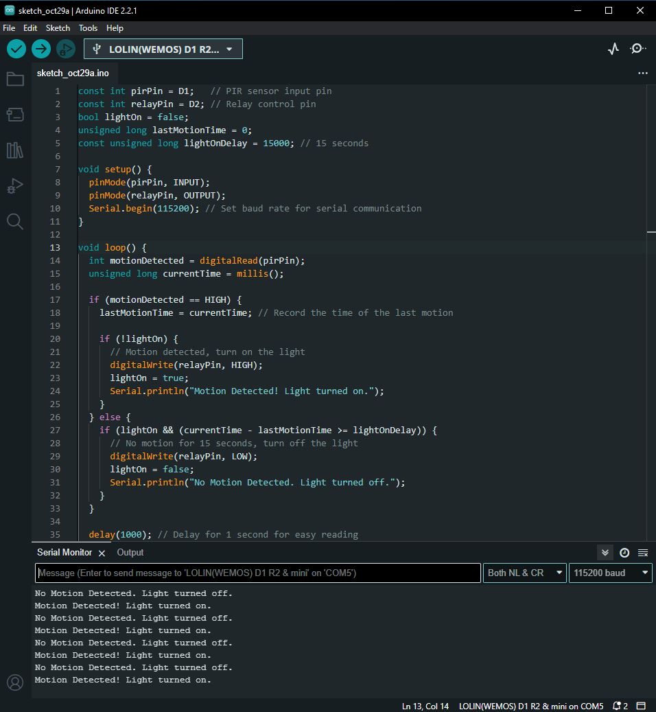
Writing the Code
const int pirPin = D1;   // PIR sensor input pin
const int relayPin = D2; // Relay control pin
bool lightOn = false;
unsigned long lastMotionTime = 0;
const unsigned long lightOnDelay = 15000; // 15 seconds

void setup() {
  pinMode(pirPin, INPUT);
  pinMode(relayPin, OUTPUT);
  Serial.begin(115200); // Set baud rate for serial communication
}

void loop() {
  int motionDetected = digitalRead(pirPin);
  unsigned long currentTime = millis();

  if (motionDetected == HIGH) {
    lastMotionTime = currentTime; // Record the time of the last motion

    if (!lightOn) {
      // Motion detected, turn on the light
      digitalWrite(relayPin, HIGH);
      lightOn = true;
      Serial.println("Motion Detected! Light turned on.");
    }
  } else {
    if (lightOn && (currentTime - lastMotionTime >= lightOnDelay)) {
      // No motion for 15 seconds, turn off the light
      digitalWrite(relayPin, LOW);
      lightOn = false;
      Serial.println("No Motion Detected. Light turned off.");
    }
  }

  delay(1000); // Delay for 1 second for easy reading
}
Checking the code
- Variable Declarations and Initialization:
pirPinandrelayPin: These variables define the GPIO pins to which the PIR sensor and KY-019 relay module are connected.lightOn: A boolean variable that keeps track of whether the light is currently turned on or off.lastMotionTime: An unsigned long variable used to record the time of the last motion detection.lightOnDelay: Specifies the duration (15 seconds) for which the light should stay on after the last motion detection.
- Setup Function:
pinMode(pirPin, INPUT): Configures the PIR pin as an input to receive signals from the PIR sensor.pinMode(relayPin, OUTPUT): Configures the relay pin as an output to control the KY-019 relay.Serial.begin(115200): Initializes serial communication with a baud rate of 115200 for debugging purposes.
- Loop Function:
- The
loopfunction is the main execution loop of the program, and it continuously runs in a loop.
- The
- Motion Detection:
int motionDetected = digitalRead(pirPin): Reads the state of the PIR sensor (HIGH or LOW) and stores it in themotionDetectedvariable.
- Motion Detection Handling:
- If
motionDetectedis HIGH (motion detected):- Checks if
lightOnisfalse, which means the light is currently off. - If the light is off, it turns on the light by setting
relayPinto HIGH, which activates the relay, and updateslightOntotrue. It also prints a message to the serial monitor. - Records the current time as
lastMotionTime.
- Checks if
- If
- No Motion Handling:
- If
motionDetectedis LOW (no motion detected):- Checks if
lightOnistrue, which means the light is currently on. - If the light is on and the time since the last motion (
currentTime - lastMotionTime) is greater than or equal to the specifiedlightOnDelay(15 seconds), it turns off the light by settingrelayPinto LOW, deactivating the relay, and updateslightOntofalse. It also prints a message to the serial monitor.
- Checks if
- If
- Delay:
delay(1000): Introduces a 1-second delay in each iteration of the loop for easier reading and to reduce unnecessary sensor readings.
Overall, this code controls a light system based on PIR sensor input. When motion is detected, it turns on the light and keeps it on for 15 seconds after the last motion is detected. If no motion is detected for this duration, it turns off the light. This approach helps save energy and ensures that the light stays on only when needed.
Uploading the Code
- Connect your ESP8266 to your computer using a USB cable.
- In the Arduino IDE, select the correct board and port under “Tools.”
- Click the “Upload” button to upload the code to your ESP8266.
Testing and Calibration
After uploading the code, power up your ESP8266 and motion sensor. The system should now automatically turn on the light when motion is detected and turn it off after a specified time.
You can adjust the delay in the code to change how long the light remains on after detecting motion.
Conclusion
Congratulations! You’ve created your intelligent light system using a KY-019 relay, ESP8266, and PIR HC-SR501 motion sensor. This system is a great foundation for further customization and integration into your home automation setup. Enjoy the convenience of hands-free lighting control in your space.