Exploring the ESP8266 Hardware Timer – LED
In this blog post, we will explore and discuss the hardware Timers available for ESP8266 boards. The code utilizes the ESP8266 timers to handle interrupts efficiently and uses a library written by Khoi Hoang.
Introduction to ESP8266 Timers
The ESP8266 is a popular microcontroller with built-in WiFi capabilities, but it has limited hardware timers available. This code addresses this limitation by providing a solution for precise timing and interrupts. Let’s dive into the code to understand its key components and functionality.
The Problem
The ESP8266 timers have limitations, such as a 23-bit counter and a maximum 256 prescaler. This results in a relatively short maximum timer interval. For example, with a 256 prescaler, the maximum interval is only about 26.84 seconds.
The Solution
This code introduces 16 Interrupt Service Routine (ISR)-based timers that significantly extend the maximum interval, limited only by an unsigned long representing milliseconds. These timers are highly accurate and can be used for mission-critical tasks.
Requirements
- Two ESP8266 development boards (e.g., NodeMCU or Wemos D1 Mini) (Affiliate) – https://s.click.aliexpress.com/e/_DD3JQhj
- Breadboard and jumper wires (Affiliate) – https://s.click.aliexpress.com/e/_Dl5kuk1
- One LED
- One 220-ohm resistor
- Arduino IDE with ESP8266 core installed
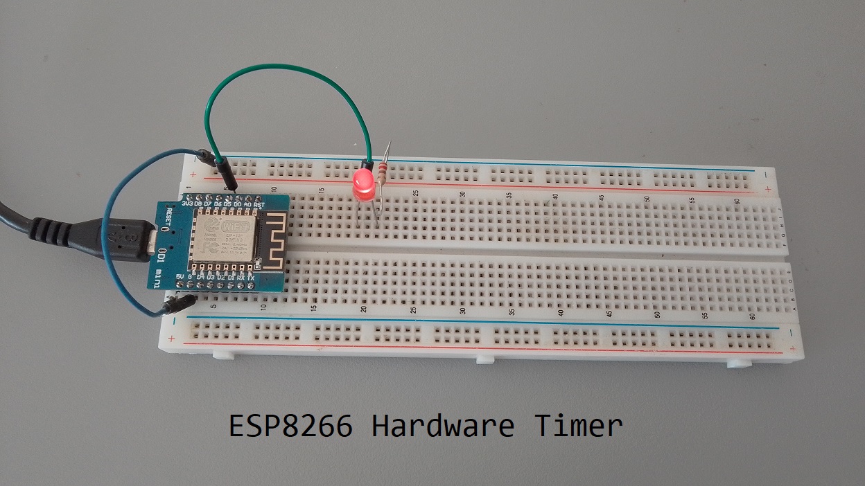
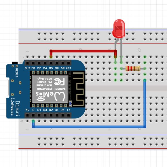
Connect Your Hardware
- Connect the LED’s anode (longer leg) to (D5) through a 220-ohm resistor.
- Connect the LED’s cathode (shorter leg) to GND.
Library installation
- Go to Sketch > Include Library > Manage Libraries…
- In the Library Manager, type “esp8266timerinterrupt” into the search box.
- Click on “ESP8266TimerInterrupt” by Khoi Hoang and click “Install”.

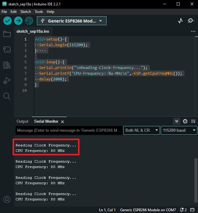
Check the clock frequency of a Wemos D1 Mini (Optional)
The Wemos D1 Mini board is based on the ESP8266 microcontroller, and you can access its clock frequency information through the ESP8266 core libraries. Here is the code:
void setup() {
  Serial.begin(115200);
}

void loop() {
  Serial.println("\nReading Clock Frequency...");
  Serial.printf("CPU Frequency: %u MHz\n", ESP.getCpuFreqMHz());
  delay(2000);
}
After opening the Serial Monitor, you should see the CPU frequency printed to the monitor. The CPU frequency is the clock frequency of the ESP8266 core.
Complete Main Code
/****************************************************************************************************************************
  TimerInterruptTest.ino
  For ESP8266 boards
  Written by Khoi Hoang

  Changed by: LT
*****************************************************************************************************************************/


// These define's must be placed at the beginning before #include "ESP8266TimerInterrupt.h"
// _TIMERINTERRUPT_LOGLEVEL_ from 0 to 4
// Don't define _TIMERINTERRUPT_LOGLEVEL_ > 0. Only for special ISR debugging only. Can hang the system.
#define TIMER_INTERRUPT_DEBUG         1
#define _TIMERINTERRUPT_LOGLEVEL_     1

// Select a Timer Clock
#define USING_TIM_DIV1                false           // for shortest and most accurate timer
#define USING_TIM_DIV16               true           // for medium time and medium accurate timer
#define USING_TIM_DIV256              false            // for longest timer but least accurate. Default

#include "ESP8266TimerInterrupt.h"

#define LED     14     // Pin D4 mapped to pin GPI14 of WeMoS

volatile bool statusLed = false;
volatile uint32_t lastMillis = 0;

#define TIMER_INTERVAL_MS       1000

// Init ESP8266 timer 1
ESP8266Timer ITimer;

//=======================================================================
void IRAM_ATTR TimerHandler()
{
  static bool started = false;

  if (!started)
  {
    started = true;
    pinMode(LED, OUTPUT);
  }

  digitalWrite(LED, statusLed);  //Toggle LED Pin
  statusLed = !statusLed;

#if (TIMER_INTERRUPT_DEBUG > 0)
  Serial.println("Delta ms = " + String(millis() - lastMillis));
  lastMillis = millis();
#endif
}
//=======================================================================
//                               Setup
//=======================================================================
void setup()
{
  Serial.begin(115200);

  while (!Serial && millis() < 5000);

  delay(500);

  Serial.print(F("\nStarting TimerInterruptTest on "));
  Serial.println(ARDUINO_BOARD);
  Serial.println(ESP8266_TIMER_INTERRUPT_VERSION);
  Serial.print(F("CPU Frequency = "));
  Serial.print(F_CPU / 1000000);
  Serial.println(F(" MHz"));

  // Interval in microsecs
  if (ITimer.attachInterruptInterval(TIMER_INTERVAL_MS * 1000, TimerHandler))
  {
    lastMillis = millis();
    Serial.print(F("Starting ITimer OK, millis() = "));
    Serial.println(lastMillis);
  }
  else
    Serial.println(F("Can't set ITimer correctly. Select another freq. or interval"));

}
//=======================================================================
//                MAIN LOOP
//=======================================================================
void loop()
{
}
Code Walkthrough
Now, let’s break down the code to understand how it works:
Timer Clock Selection
You can choose the timer clock division factor by setting one of the following defines:
USING_TIM_DIV1: Shortest and most accurate timer.USING_TIM_DIV16: Medium time and medium accuracy timer.USING_TIM_DIV256: Longest timer but least accurate (default).
Library Inclusion
The code includes the ESP8266TimerInterrupt.h library, which provides the functionality for creating ISR-based timers.
Pin Definitions
#define LED 14 // Pin D4 mapped to pin GPI14 of WeMoS
This defines the pin for the LED, which is GPIO14.
Global Variables
volatile bool statusLed = false;
volatile uint32_t lastMillis = 0;
These variables are marked as volatile because they are accessed both within the main loop and the interrupt handler. The statusLed variable is used to toggle the LED state, and lastMillis records the last time the interrupt occurred.
Timer Handler Function
void IRAM_ATTR TimerHandler()
{
  static bool started = false;

  if (!started)
  {
    started = true;
    pinMode(LED, OUTPUT);
  }

  digitalWrite(LED, statusLed);  //Toggle LED Pin
  statusLed = !statusLed;

#if (TIMER_INTERRUPT_DEBUG > 0)
  Serial.println("Delta ms = " + String(millis() - lastMillis));
  lastMillis = millis();
#endif
}
This is the interrupt handler function that gets executed at a specified interval. It toggles the LED, allowing you to see the effect of the interrupt. It also logs the time difference between interrupts if debugging is enabled.
Setup Function
void setup()
{
  // Serial initialization and delay for serial connection
  Serial.begin(115200);
  while (!Serial && millis() < 5000);
  delay(500);

  // Print information about the board and timers
  Serial.print(F("\nStarting TimerInterruptTest on "));
  Serial.println(ARDUINO_BOARD);
  Serial.println(ESP8266_TIMER_INTERRUPT_VERSION);
  Serial.print(F("CPU Frequency = "));
  Serial.print(F_CPU / 1000000);
  Serial.println(F(" MHz"));

  // Attach the interrupt handler to a timer with a specified interval
  if (ITimer.attachInterruptInterval(TIMER_INTERVAL_MS * 1000, TimerHandler))
  {
    lastMillis = millis();
    Serial.print(F("Starting ITimer OK, millis() = "));
    Serial.println(lastMillis);
  }
  else
    Serial.println(F("Can't set ITimer correctly. Select another freq. or interval"));
}
In the setup function, the code initializes the serial communication, prints board information, and attaches the TimerHandler function to an interrupt timer with the specified interval (in microseconds).
Main Loop
void loop()
{
  // The loop is intentionally left empty because the main functionality is driven by the interrupt.
}
The main loop is left empty as the core functionality is handled by the interrupt handler. The interrupt will toggle the LED and log the time difference between interrupts if debugging is enabled.
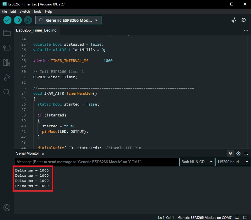
Result
Pressing the Reset button on the Board (If all is connected correctly), we can see information related to the board and timer.

Then the timer will display the value in milliseconds (1 Second) that is the time the led remains On (1 Second) and Then Off (1 Second)
Conclusion
In this blog post, we explored the Timer code designed for ESP8266 boards. This code addresses the limitations of ESP8266 timers by providing ISR-based timers with extended intervals and high accuracy. It’s a valuable resource for applications that require precise timing and interrupt handling.
You can find the full code and documentation on the GitHub repository created by Khoi Hoang. Feel free to explore and use it for your ESP8266-based projects.