
ESP8266: Connecting a Keypad via I2C with PCF8574
The ESP8266 is a powerful and popular microcontroller often used in IoT and DIY projects. However, it has a limited number of GPIO pins, which can be a constraint when you need to interface with multiple input or output devices. In this tutorial, we will explore how to overcome this limitation by connecting a PCF8574 I2C I/O expander to an ESP8266 and using it to interface with a 4×3 keypad.
Prerequisites
Before we dive into the tutorial, make sure you have the following components:
- ESP8266 development board (e.g., NodeMCU or Wemos D1 Mini) (Affiliate) – https://s.click.aliexpress.com/e/_DD3JQhj
- PCF8574 I2C I/O expander (Affiliate) – https://s.click.aliexpress.com/e/_DlatchV
- 4×3 keypad (Affiliate) – https://s.click.aliexpress.com/e/_Dk5oIjl
- Breadboard and jumper wires (Affiliate) – https://s.click.aliexpress.com/e/_Dl5kuk1
- Arduino IDE or compatible development environment
Goodies:
- Datasheet: Link to Download
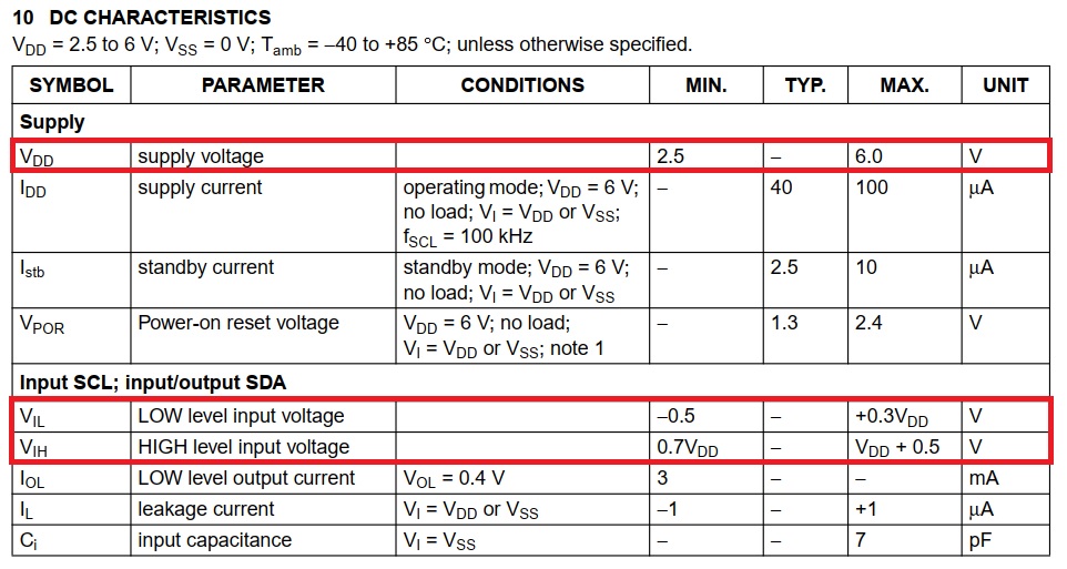
From the datasheet we can see the values that are important. The first one is VDD and tells us that the module can operate between 2.5 and 6 Volt. The second is the logic levels voltage Vil and Vih. Has the Esp8266 is only 3.3V tolerant then we can power the module with 3.3 Volt and it will be OK.
The Schematic: Link to Download
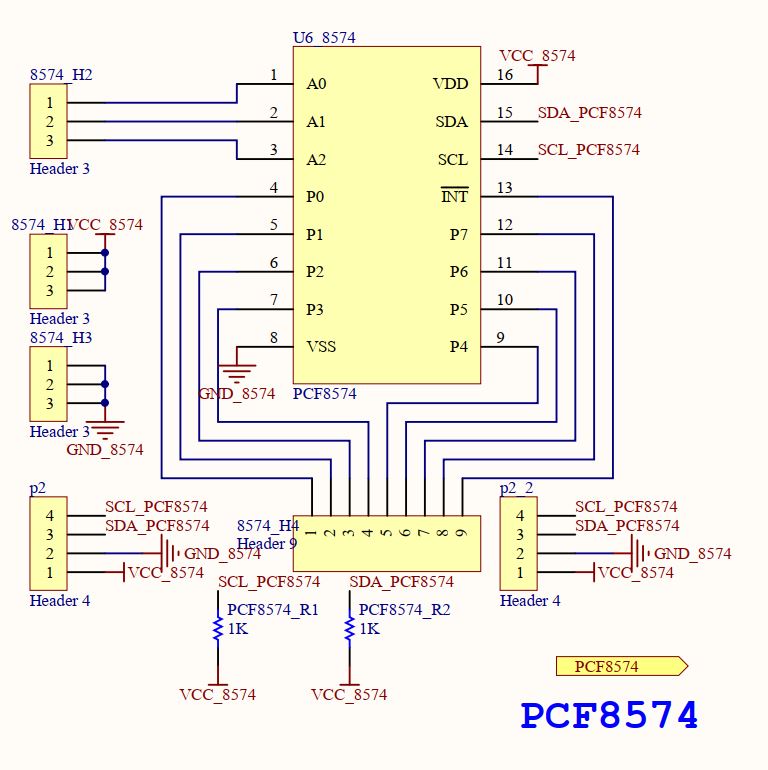
The PCF8574
The PCF8574 features 8 general-purpose I/O pins that can be independently configured as either inputs or outputs. These pins can be used to interface with various external devices such as buttons, switches, sensors, or actuators. The device communicates with the host controller through the I2C bus, a popular serial communication protocol.
Here are some key features and characteristics of the PCF8574 I/O expander:
- I2C Interface: The PCF8574 communicates with the host microcontroller or device through the I2C bus, which is a two-wire serial interface. This allows multiple PCF8574 devices (up to 8) to be connected in a master-slave configuration, utilizing only two wires for communication. Each of the 8 I/O pins of the PCF8574 can be individually configured as either inputs or outputs. This flexibility allows you to adapt the device to meet your specific needs The PCF8574 module is ideal for large projects or where the microcontroller pins are not enough. Additionally, you can connect up to 8 PCF8574 modules in series in one project, totaling 64 input/output ports.
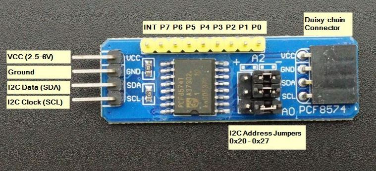
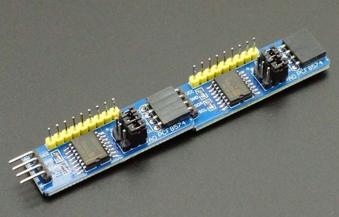
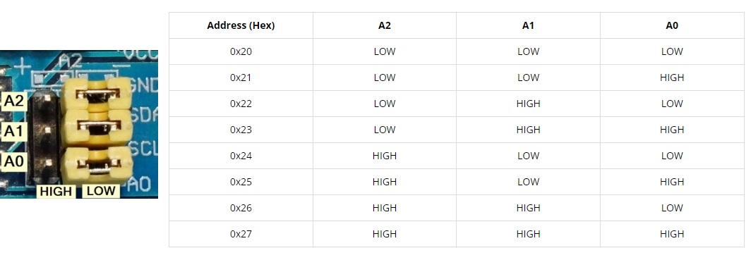
- The module has an easy to use I2C interface that can be configured to use any one of eight different I2C addresses if you want to use multiple modules in the same system or if you run into an address conflict with another device. This puts the module at the base address of 0x20. The jumpers can be moved in a binary fashion to increase the address, so the address can range from 0x20 to 0x27 as shown in the table below. If you daisy-chain the modules, you will need to set a different address for each of the modules.
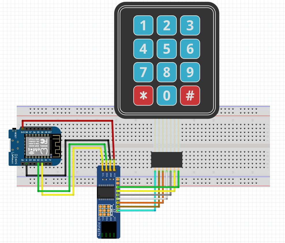
Step 1: Wiring Connections
The first step is to connect the PCF8574, 4×3 keypad, and ESP8266. Here’s how to make the connections:
- Connect VCC of the PCF8574 to a 3.3 Volt External Regulated Power Source (or to the ESP8266’s 3.3V pin).
- Connect GND of the PCF8574 to the ESP8266’s GND/Global GND pins.
- Connect SDA of the PCF8574 to the ESP8266’s D2 pin (SDA – Serial Data).
- Connect SCL of the PCF8574 to the ESP8266’s D1 pin (SCL – Serial Clock).
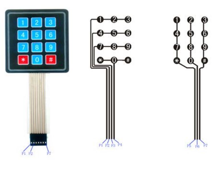
For the 4×3 keypad:
- Connect the four rows (usually labeled as P1, P2, P3, P4) to the other four pins on the PCF8574 (e.g., P0, P1, P2, P3). These will be the output pins.
- Connect the three columns (usually labeled as P5, P6, P7) to three of the PCF8574’s pins (e.g., P4, P5, P6). These will serve as input pins.
- Version 1 -> 3.3Volt from Esp8266
- Version 2 -> 3.3Volt from External Regulated Power Source

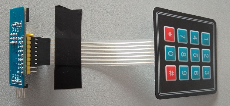
- Detail: Connection from PCF8574 to the Membrane Keypad

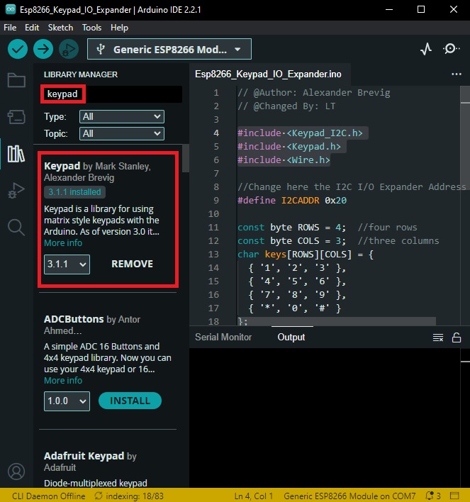
Step 2: Install Required Libraries
To work with the PCF8574 and the keypad, you need to install two libraries: “Keypad_I2C” and “Keypad.”
- Keypad_I2C.h
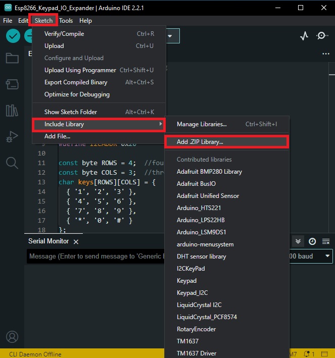

- Keypad.h
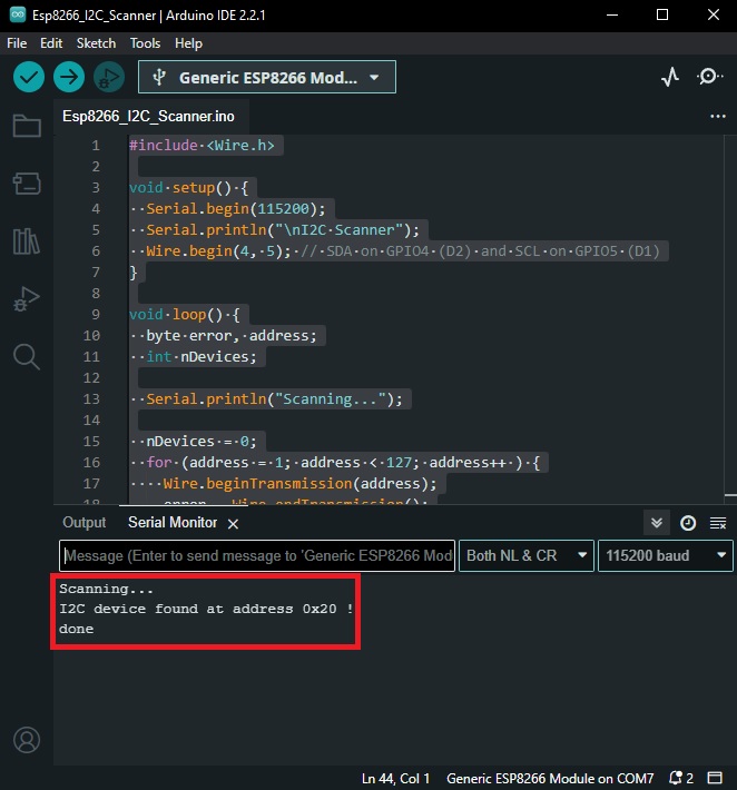
Checking the Address using I2C Scanner
The address of the PCF8574 port expander module can be obtained by referring to Table 1. To make sure the address is correct, we can run an example code:
#include <Wire.h>

void setup() {
  Serial.begin(115200);
  Serial.println("\nI2C Scanner");
  Wire.begin(4, 5); // SDA on GPIO4 (D2) and SCL on GPIO5 (D1)
}

void loop() {
  byte error, address;
  int nDevices;

  Serial.println("Scanning...");

  nDevices = 0;
  for (address = 1; address < 127; address++ ) {
    Wire.beginTransmission(address);
    error = Wire.endTransmission();

    if (error == 0) {
      Serial.print("I2C device found at address 0x");
      if (address < 16) {
        Serial.print("0");
      }
      Serial.print(address, HEX);
      Serial.println(" !");

      nDevices++;
    } else if (error == 4) {
      Serial.print("Unknown error at address 0x");
      if (address < 16) {
        Serial.print("0");
      }
      Serial.println(address, HEX);
    }
  }
  if (nDevices == 0) {
    Serial.println("No I2C devices found\n");
  } else {
    Serial.println("done\n");
  }
  delay(5000);
}
The valid result will be this:
Step 3: Writing the Arduino Sketch
Now, let’s check the Arduino sketch to read and interpret keypad inputs via the PCF8574 and ESP8266. Here’s the code:
// @Author: Alexander Brevig
// @Changed By: LT

#include <Keypad_I2C.h>
#include <Keypad.h>
#include <Wire.h>

//Change here the I2C I/O Expander Address
#define I2CADDR 0x20

const byte ROWS = 4;  //four rows
const byte COLS = 3;  //three columns
char keys[ROWS][COLS] = {
  { '1', '2', '3' },
  { '4', '5', '6' },
  { '7', '8', '9' },
  { '*', '0', '#' }
};

// Numbers of PCF8574 i/o port
byte rowPins[ROWS] = { 0, 1, 2, 3 };  //connect to the row pinouts of the keypad
byte colPins[COLS] = { 4, 5, 6 };     //connect to the column pinouts of the keypad

TwoWire *jwire = &Wire;  //test passing pointer to keypad lib
Keypad_I2C kpd(makeKeymap(keys), rowPins, colPins, ROWS, COLS, I2CADDR, PCF8574, jwire);


void setup() {
  Serial.begin(115200);
  jwire->begin();
  kpd.begin();
}
void loop() {
  char key = kpd.getKey();

  if (key) {
    Serial.println(key);
  }
}
In this code:
#include <Keypad_I2C.h>,#include <Keypad.h>: They are library files. You are including the keypad libraries for Arduino to make it easier to interact with the keypad.#include <Wire.h>: Wire Library, this library allows for communicating with I2C devices.#define I2CADDR 0x20: The I2C address of the keypad.const byte ROWS = 4;: The keypad used here has 4 rowsconst byte COLS = 3;: The keypad used here has 3 columns.Char keys[ROWS][COLS]: It’s a 2D array storing the keys/buttons on the keypad.byte rowPins[ROWS] = { 0, 1, 2, 3 };andbyte colPins[COLS] = { 4, 5, 6 };These define which I/O pins on the I2C expander are connected to the rows and columns of the keypad respectively.TwoWire *jwire = &Wire; //test passing pointer to keypad lib: Initializes TwoWire object.void setup() { Serial.begin(115200); jwire->begin(); kpd.begin(); }: This is a function that runs once when the program starts. It is used to set the baud rate for serial data transmission, while jwire->begin() and kpd.begin() initialize the I2C communication and the keypad.void loop() { char key = kpd.getKey(); if (key) { Serial.println(key); } }: This function runs in a loop as long as the Arduino has power. It’s checking to see if a key is being pressed on the keypad, and if a key is pressed, it prints that key to the Arduino’s Serial Monitor.
This code only outputs to the serial monitor, so to make it practical, you would need to add something to be controlled by the keypad buttons.
Step 4: Upload and Test
Upload the code to your ESP8266 board using the Arduino IDE or your preferred development environment. Open the Serial Monitor ) to see the output when you press keys on the keypad. The ESP8266 should display the pressed keys in the Serial Monitor.

Conclusion
In this tutorial, you learned how to connect a PCF8574 I2C I/O expander and a 4×3 keypad to an ESP8266 microcontroller. By doing so, you can expand the number of available GPIO pins on your ESP8266 and easily interface with input devices like keypads. This opens up possibilities for a wide range of projects that require more GPIO pins than the ESP8266 provides natively.