ESP-01 and Breadboard Adapter: External LED Control
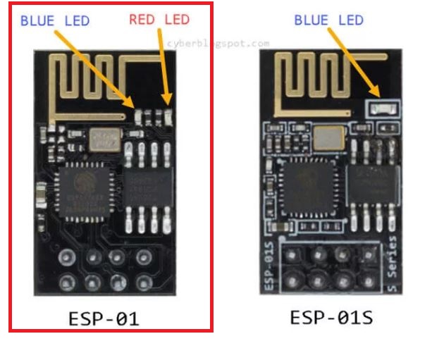
The ESP-01 is a popular and inexpensive Wi-Fi module based on the ESP8266 chip. It is widely used in IoT projects due to its small size and low power consumption. In this tutorial, we will demonstrate how to connect an ESP-01 board to a breadboard adapter and control an external LED. This setup can be easily expanded to control other devices or sensors in your IoT projects.
Requirements:
- ESP-01 Wi-Fi module (Affiliate) – https://s.click.aliexpress.com/e/_DETsfWR
- Breadboard adapter for ESP-01 (Affiliate) – https://s.click.aliexpress.com/e/_DC3gXdN
- Breadboard and jumper wires (Affiliate) – https://s.click.aliexpress.com/e/_Dl5kuk1
- External LED
- 220-ohm resistor
- Jumper wires
- USB ESP-01 Programming Adapter with a CH340G chip (Affiliate) – https://s.click.aliexpress.com/e/_DETsfWR
- Arduino IDE or any other ESP8266 compatible programming environment
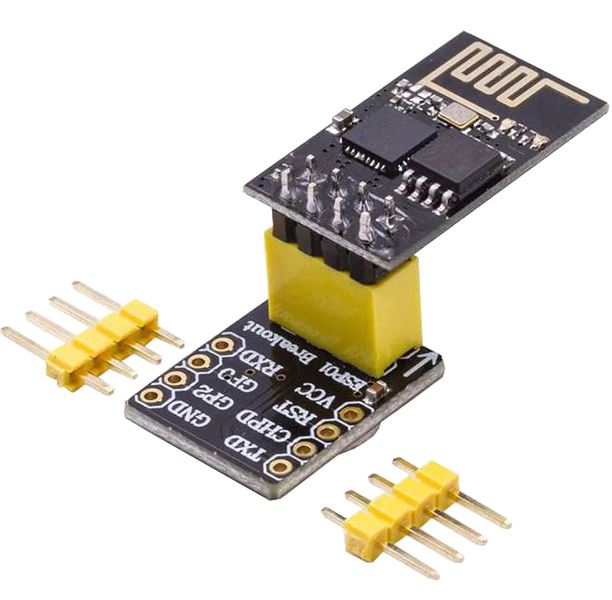
Step 1: Connecting the ESP-01 to the Breadboard Adapter
Boot from flash
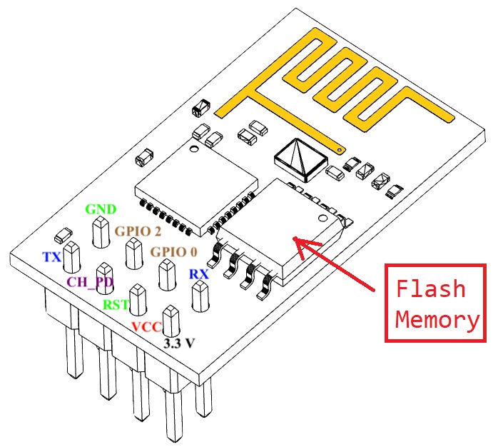
To boot from flash (Flash memory for the Esp-01), we need to make the following connections:
- Connect VCC to 3.3 V
- Connect GND to ground.
- Connect GPIO0 to 3.3 V.
- Connect EN/CHPD to 3.3 V.
I am going to use an external regulated 3.3v power source to power the board. (The Esp-01 it is only 3.3v tolerant)
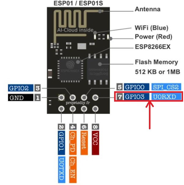
- I connected the external led to the UORXD Pin. This is because we have the flickering problem on boot for other Pins (the Pin goes HIGH to LOW for a brief period of time). Curiously, this didn’t happened with this pin. The UORXD can also be used as GPIO3.
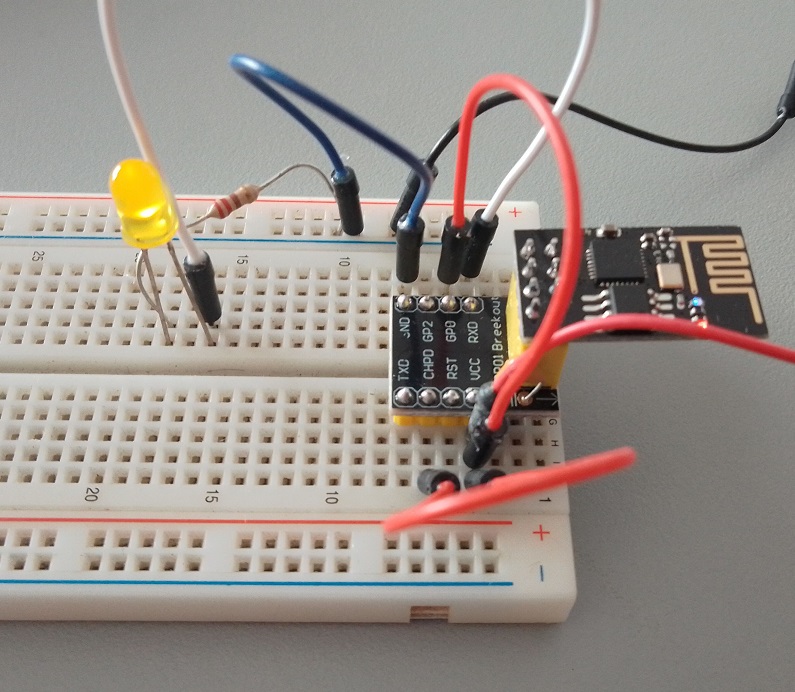
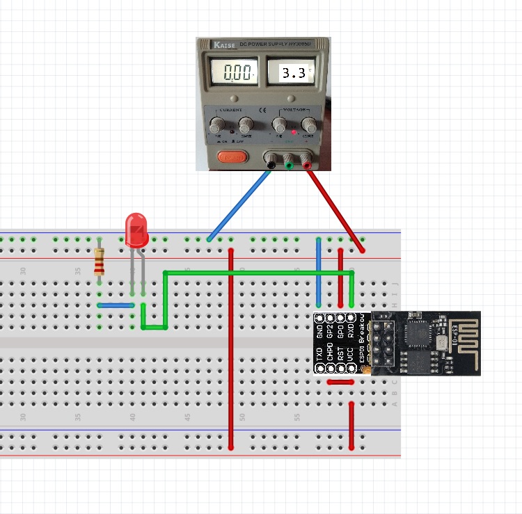
Step 2: Setting up the Breadboard and External LED
Place the breadboard adapter with the ESP-01 module on the breadboard. Make all the connections.
- Connect VCC to 3.3 V and GND to ground.
- Connect GPIO0 to 3.3 V.
- Connect EN/CHPD to 3.3 V.
- Insert the external LED into the breadboard. Connect the longer leg (anode) of the LED to the RXD pin on the breadboard adapter.
- Insert a 220-ohm resistor into the same row as the shorter leg (cathode) of the LED. Connect the other end of the resistor to the ground rail on the breadboard.
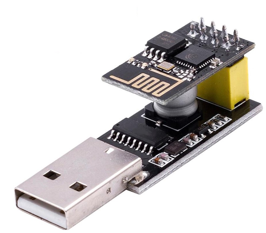
Step 5: Connecting the USB to TTL Converter
To put the CH340G adapter in programming mode, follow these steps:
- Before plugging the USB ESP-01 programming adapter into a USB port on your computer, Press and hold the push button switch that you soldered in Step 2 for a few seconds.
- Plug the USB ESP-01 programming adapter into a USB port on your computer with the button pressed.
- Release the button: After a few seconds, release the push button switch. The Esp-01 should be in programming mode, and you can upload code to the ESP-01 module using your preferred development environment.
If having trouble, go to my previous blog post. It explains with images: https://www.edgemicrotech.com/preparing-the-usb-esp-01-programming-adapter-a-step-by-step-guide/
Step 6: Programming the ESP-01
Open the Arduino IDE or your preferred programming environment. Install the ESP8266 board package if you haven’t already. Select the “Generic ESP8266 Module” as the board type.
Upload the following code to the ESP-01:
const int ledPin = 3;

void setup() {
  pinMode(ledPin, OUTPUT);
}

// the loop function runs over and over again forever
void loop() {
  digitalWrite(ledPin, LOW);
  delay(1000);
  digitalWrite(ledPin, HIGH);
  delay(1000);
}
- This code will make the external LED blink with a 1-second interval.
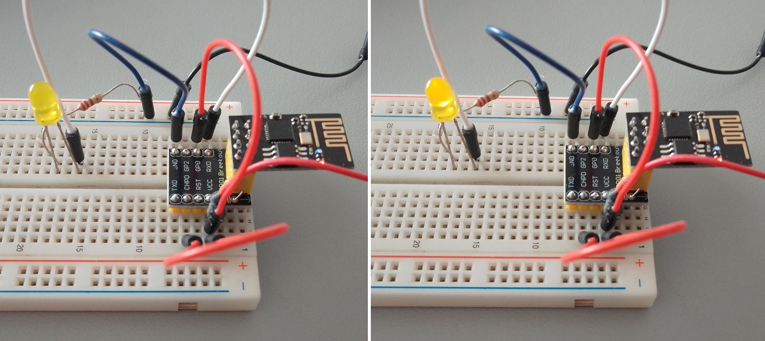
Step 7: Testing the LED
- Once the code is uploaded, remove the Esp-01 from the USB adapter an put it on the breadboard adapter. Pay attention to the direction of the board.

- Double check all the connections and the external power source before powering the circuit.
- When you are sure the everything is OK, turn on the power source and the External Led should start to blink.
Conclusion:
In this tutorial, we demonstrated how to connect an ESP-01 board to a breadboard adapter and control an external LED. This basic setup can be expanded to control other devices or sensors in your IoT projects. The ESP-01 is a versatile and cost-effective solution for various wireless applications, making it an excellent choice for hobbyists and professionals alike.