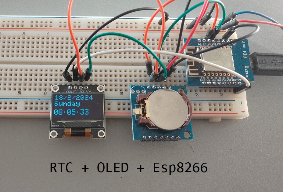
DS1307 with Esp8266 and OLED Display
In this blog post, we’ll create a real-time clock (RTC) display using Wemos D1 Mini, an OLED display, and a real-time clock module. This project will showcase the current date and time on the OLED display in a visually appealing format. By the end of this tutorial, you’ll have a working RTC display that you can use as a clock or integrate into other projects.
Introduction
Real-time clocks (RTCs) are essential components in many embedded systems, allowing accurate timekeeping even when the main microcontroller is powered off. Combining an RTC module with an Esp8266 microcontroller and an OLED display provides a convenient way to visualize the current time and date.
Components Needed
To build this project, you’ll need the following components:
- ESP8266 Development Board (such as NodeMCU) (Affiliate) – https://s.click.aliexpress.com/e/_DD3JQhj
- OLED Display (128×64 pixels) (Affiliate) – https://s.click.aliexpress.com/e/_Dm4UE3J
- DS1307 AT24C32 RTC Module (Affiliate) – https://s.click.aliexpress.com/e/_DlYHuVj
- Breadboard and jumper wires (Affiliate) – https://s.click.aliexpress.com/e/_Dl5kuk1
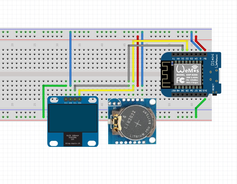
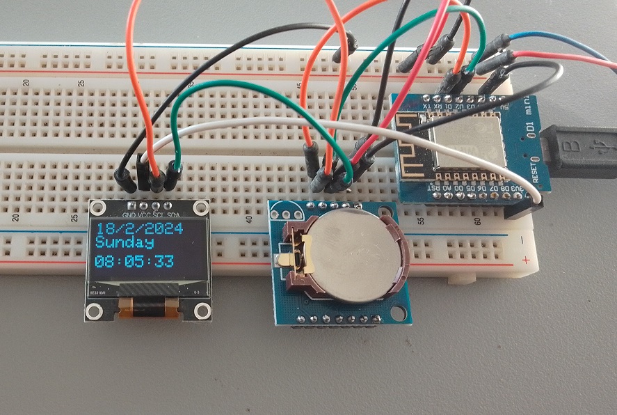
Circuit Diagram
Connect the components as follows:

- OLED display:
- SDA pin to Wemos D1 Mini pin D2
- SCL pin to Wemos D1 Mini pin D1
- VCC to Wemos D1 Mini 3.3V
- GND to Wemos D1 Mini GND
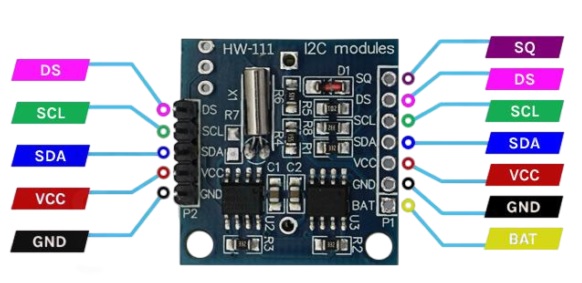
- RTC module:
- SDA pin to Wemos D1 Mini pin D2
- SCL pin to Wemos D1 Mini pin D1
- VCC to Wemos D1 Mini 5V
- GND to Wemos D1 Mini GND
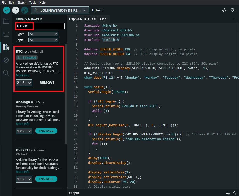
Gather Necessary Libraries
Before starting the project, make sure you have the necessary libraries installed. Open the Arduino IDE and navigate to Sketch -> Include Library -> Manage Libraries. Search for and install the following libraries:
Adafruit_GFX
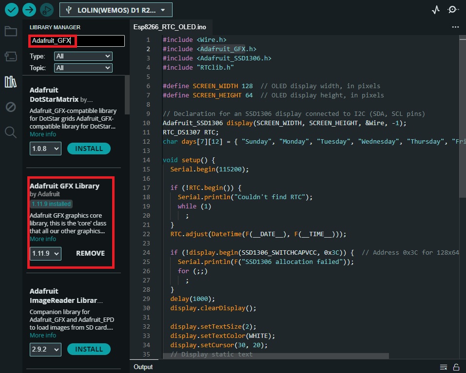
Adafruit_SSD1306

RTClib (Also from Adafruit)
The Code
#include <Wire.h>
#include <Adafruit_GFX.h>
#include <Adafruit_SSD1306.h>
#include "RTClib.h"

#define SCREEN_WIDTH 128  // OLED display width, in pixels
#define SCREEN_HEIGHT 64  // OLED display height, in pixels

// Declaration for an SSD1306 display connected to I2C (SDA, SCL pins)
Adafruit_SSD1306 display(SCREEN_WIDTH, SCREEN_HEIGHT, &Wire, -1);
RTC_DS1307 RTC;
char days[7][12] = { "Sunday", "Monday", "Tuesday", "Wednesday", "Thursday", "Friday", "Saturday" };

void setup() {
  Serial.begin(115200);

  if (!RTC.begin()) {
    Serial.println("Couldn't find RTC");
    while (1)
      ;
  }
  RTC.adjust(DateTime(F(__DATE__), F(__TIME__)));

  if (!display.begin(SSD1306_SWITCHCAPVCC, 0x3C)) {  // Address 0x3C for 128x64
    Serial.println(F("SSD1306 allocation failed"));
    for (;;)
      ;
  }
  delay(1000);
  display.clearDisplay();

  display.setTextSize(2);
  display.setTextColor(WHITE);
  display.setCursor(30, 20);
  // Display static text
  display.println("RTC");
  display.display();
  delay(3000);
  display.clearDisplay();
}

void loop() {
  DateTime now = RTC.now();

  display.clearDisplay();
  display.setTextSize(2);
  display.setCursor(0, 0);
  display.print(now.day());
  display.print('/');
  display.print(now.month());
  display.print('/');
  display.print(now.year());
  display.println(' ');
  display.println(days[now.dayOfTheWeek()]);
  display.println(' ');
  display.setCursor(0, 40);
  if (now.hour() < 10)
    display.print('0');
  display.print(now.hour());
  display.print(':');
  if (now.minute() < 10)
    display.print('0');
  display.print(now.minute());
  display.print(':');
  if (now.second() < 10)
    display.print('0');
  display.println(now.second());
  display.display();
}
Code Explanation
This code is for an Arduino sketch that interfaces with a real-time clock (RTC) module and an OLED display to show the current date and time. Let’s break it down step by step:
- Include Libraries: The code begins by including several libraries required for the project:
Wire.h: This library allows communication over the I2C bus.Adafruit_GFX.handAdafruit_SSD1306.h: These libraries are for controlling the OLED display.RTClib.h: This library provides functionality to interact with the RTC module.
- Constants and Variables: The code defines some constants and variables:
SCREEN_WIDTHandSCREEN_HEIGHT: Constants representing the dimensions of the OLED display.Adafruit_SSD1306 display: An object of theAdafruit_SSD1306class representing the OLED display.RTC_DS1307 RTC: An object representing the real-time clock module.days[7][12]: A 2D array storing the names of the days of the week.
- Setup Function (
void setup()):- The
setup()function initializes serial communication and checks if the RTC module is connected. - It sets the current time of the RTC module to the compilation time of the sketch.
- Initializes the OLED display and prints “RTC” on it for 3 seconds.
- The
- Loop Function (
void loop()):- The
loop()function runs continuously. - It retrieves the current date and time from the RTC module.
- Clears the OLED display and prints the date, day of the week, and time.
- It then updates the display with this information.
- The
- Display Format:
- The date is printed in the format “dd/mm/yyyy”.
- The day of the week is obtained from the
daysarray based on the current day. - The time is printed in the format “hh:mm:ss”.
- Display Update: The display is updated with the current date and time in every iteration of the loop.
FAQ
To update the time, we have to connect and upload this sketch every time?
No, you don’t need to connect and upload the sketch every time you want to update the time on the RTC module. The provided line RTC.adjust(DateTime(F(__DATE__), F(__TIME__))); is useful for setting the initial time during development or when setting up the RTC module for the first time.
Once the RTC module is initialized with the correct time, it will continue to keep time accurately even when the Esp8266 board is powered off or reset. You typically only need to set the time manually when you initially set up the project or if the RTC module loses power or encounters other issues that cause it to lose its stored time.
What are the default I2C addresses for OLED displays and RTC modules?
- OLED Display: The default I2C address for most SSD1306-based OLED displays is
0x3C. However, some displays may also use0x3D. It’s essential to check the datasheet or product documentation for your specific OLED display to confirm the address. - RTC Module: The default I2C address for popular RTC modules like DS1307, DS3231, and similar ones is
0x68. However, some modules may have alternative addresses that can be set using hardware jumpers or software configurations.
Keep in mind that these are the default addresses, and they can be different based on various factors such as manufacturer, module variant, or configuration settings. Always refer to the datasheets or product documentation provided by the manufacturer to determine the correct I2C addresses for your specific components.
Conclusion
In this tutorial, we’ve demonstrated how to create a real-time clock (RTC) display using an Esp8266, OLED display, and an RTC module. This project provides a foundation for creating more advanced projects that require accurate timekeeping and visualization. Feel free to extend this project by adding features such as alarm functionality or temperature monitoring.