
Countdown Timer with ESP8266 and KY-040 Encoder
In this blog post, we’ll walk through the code for creating a countdown timer using an ESP8266 microcontroller and a KY-040 rotary encoder. The timer will be displayed in the serial monitor, and we’ll also provide a wiring section to help you set up the components correctly.
Components Needed:
- ESP8266 Development Board (such as Wemos D1 mini) (Affiliate) – https://s.click.aliexpress.com/e/_DD3JQhj
- KY-040 rotary encoder (Affiliate) – https://s.click.aliexpress.com/e/_Dl3uGHB
- Breadboard and jumper wires (Affiliate) – https://s.click.aliexpress.com/e/_Dl5kuk1
Wiring the Components:
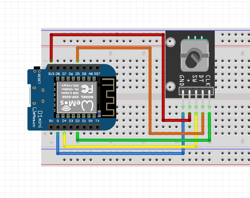
Connect the components as follows:
- Connect CLK (Clock) pin of the KY-040 encoder to D2 on the ESP8266.
- Connect DT (Data) pin of the KY-040 encoder to D5 on the ESP8266.
- Connect SW (Switch) pin of the KY-040 encoder to D4 on the ESP8266.
Code
const int CLK = D2;
const int DT = D5;
const int SW = D4;

int encoderValue = 0;
int lastCLKState;
int lastDTState;
bool buttonPressed = false;
bool timerRunning = false;
unsigned long countdownStartTime;
unsigned long countdownDuration = 0;

void setup() {
  pinMode(CLK, INPUT);
  pinMode(DT, INPUT);
  pinMode(SW, INPUT_PULLUP);

  lastCLKState = digitalRead(CLK);
  lastDTState = digitalRead(DT);

  Serial.begin(115200);
}

void loop() {
  int currentStateCLK = digitalRead(CLK);
  int currentStateDT = digitalRead(DT);

  if (currentStateCLK != lastCLKState) {
    if (currentStateCLK == HIGH) {
      // On rising edge of CLK
      if (currentStateDT == LOW) {
        // Clockwise rotation
        encoderValue++;
      } else {
        // Counter-clockwise rotation
        encoderValue--;
      }

      // Ensure encoderValue is not negative
      if (encoderValue < 0) {
        encoderValue = 0;
      }

      Serial.print("Encoder Value: ");
      Serial.println(encoderValue);

      // Convert encoder value to seconds (adjust the scale as needed)
      countdownDuration = encoderValue * 60;
    }
  }

  lastCLKState = currentStateCLK;
  lastDTState = currentStateDT;

  if (timerRunning) {
    unsigned long elapsedTime = millis() - countdownStartTime;

    if (elapsedTime < countdownDuration * 1000) {
      unsigned long remainingTime = (countdownDuration * 1000) - elapsedTime;
      int minutes = remainingTime / (60 * 1000);
      int seconds = (remainingTime % (60 * 1000)) / 1000;

      Serial.print("Remaining Time: ");
      Serial.print(minutes);
      Serial.print(" minutes and ");
      Serial.print(seconds);
      Serial.println(" seconds");
    } else {
      Serial.println("Countdown complete");
      timerRunning = false;
      Serial.println("Input enabled");
    }
  }

  if (digitalRead(SW) == LOW && !buttonPressed && !timerRunning) {
    buttonPressed = true;
    timerRunning = true;
    countdownStartTime = millis();

    Serial.print("Countdown started for ");
    Serial.print(countdownDuration / 60);
    Serial.print(" minutes and ");
    Serial.print(countdownDuration % 60);
    Serial.println(" seconds");
  } else if (digitalRead(SW) == HIGH && buttonPressed) {
    buttonPressed = false;
  }

  delay(1);
}
Understanding the Code:
Let’s break down the code step by step:
- These lines declare the pin assignments, variables for encoder values, and timer-related variables.
const int CLK = D2;
const int DT = D5;
const int SW = D4;

int encoderValue = 0;
int lastCLKState;
int lastDTState;
bool buttonPressed = false;
bool timerRunning = false;
unsigned long countdownStartTime;
unsigned long countdownDuration = 0;
- In the
setupfunction, pin modes are set, and the initial states of CLK and DT pins are read. Serial communication is initiated for debugging purposes.
void setup() {
  pinMode(CLK, INPUT);
  pinMode(DT, INPUT);
  pinMode(SW, INPUT_PULLUP);

  lastCLKState = digitalRead(CLK);
  lastDTState = digitalRead(DT);

  Serial.begin(115200);
}
- The
loopfunction continuously monitors the CLK and DT states. When a change is detected on the CLK pin, it determines the direction of rotation and updates the encoder value accordingly. The encoder value is then converted to minutes and displayed in the serial monitor.
void loop() {
  int currentStateCLK = digitalRead(CLK);
  int currentStateDT = digitalRead(DT);

  if (currentStateCLK != lastCLKState) {
    if (currentStateCLK == HIGH) {
      if (currentStateDT == LOW) {
        encoderValue++;
      } else {
        encoderValue--;
      }

      if (encoderValue < 0) {
        encoderValue = 0;
      }

      Serial.print("Encoder Value: ");
      Serial.println(encoderValue);

      countdownDuration = encoderValue * 60;
    }
  }

  lastCLKState = currentStateCLK;
  lastDTState = currentStateDT;

  // ... (code for updating the timer and handling button press)
  delay(1);
}
- The code checks if the timer is running. If yes, it calculates and displays the remaining time. When the switch (SW) is pressed and the timer is not running, it starts the countdown.
  if (timerRunning) {
    // ... (code for updating and displaying the timer)
  }

  if (digitalRead(SW) == LOW && !buttonPressed && !timerRunning) {
    // ... (code for starting the timer)
  } else if (digitalRead(SW) == HIGH && buttonPressed) {
    buttonPressed = false;
  }

  delay(1);
}
Testing
Conclusion:
With this code and the provided wiring instructions, you can build a countdown timer using an ESP8266 and a KY-040 rotary encoder. Feel free to modify the code according to your specific requirements and experiment with different features.