Connecting Two ESP8266 Modules Using ESP-NOW: A Button and a Led
ESP-NOW is a powerful communication protocol developed by Espressif for the ESP8266 and ESP32 microcontrollers. It enables devices to communicate directly with each other without the need for a Wi-Fi network. In this tutorial, we will demonstrate how to connect two ESP8266 modules using ESP-NOW, with one module controlling an LED on the other module via a button press.
Requirements
- Two ESP8266 development boards (e.g., NodeMCU or Wemos D1 Mini) (Affiliate) – https://s.click.aliexpress.com/e/_DD3JQhj
- Breadboard and jumper wires (Affiliate) – https://s.click.aliexpress.com/e/_Dl5kuk1
- One LED
- One 220-ohm resistor
- One push button
- Arduino IDE with ESP8266 core installed
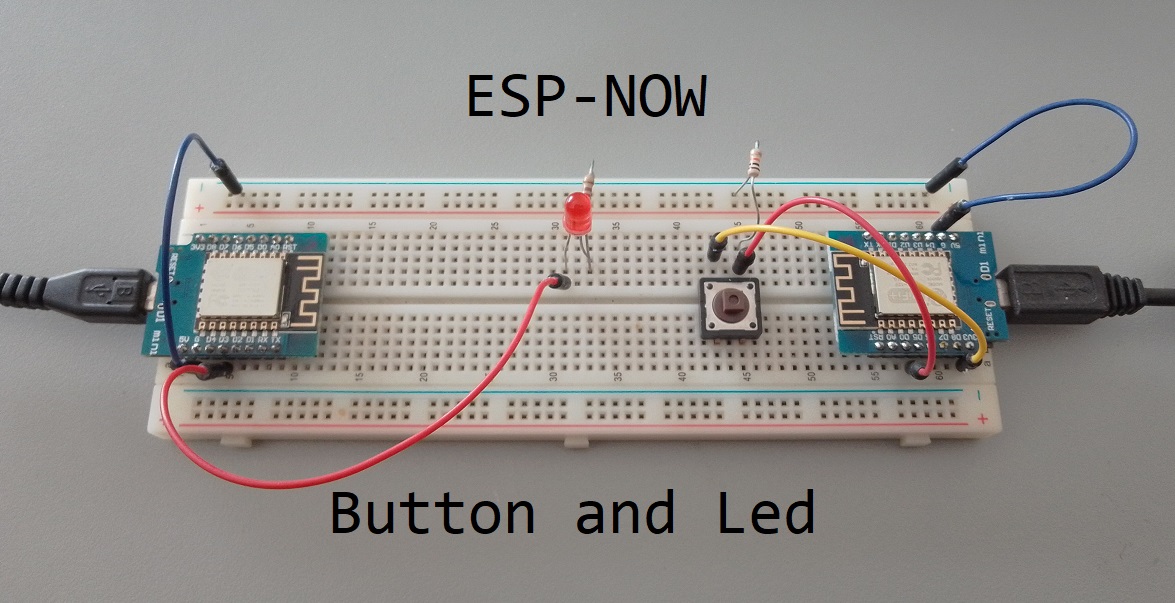
Step 1: Wiring the Circuit
First, let’s wire the circuit on the breadboard. Connect the components as follows:
Transmitter (ESP8266 with button):
- Connect the push button to (D5) and GND.
- Connect a 10k-ohm resistor between (D5) and 3.3V (pull-up resistor).
Receiver (ESP8266 with LED):
- Connect the LED’s anode (longer leg) to (D3) through a 220-ohm resistor.
- Connect the LED’s cathode (shorter leg) to GND.

Step 2: Setting Up the Arduino IDE
- Open the Arduino IDE.
- Go to File > Preferences and add the ESP8266 board manager URL (http://arduino.esp8266.com/stable/package_esp8266com_index.json) to the “Additional Boards Manager URLs” field.
- Go to Tools > Board > Boards Manager, search for “esp8266,” and install the “esp8266” package by ESP8266 Community.
- Select the appropriate ESP8266 board from Tools > Board.
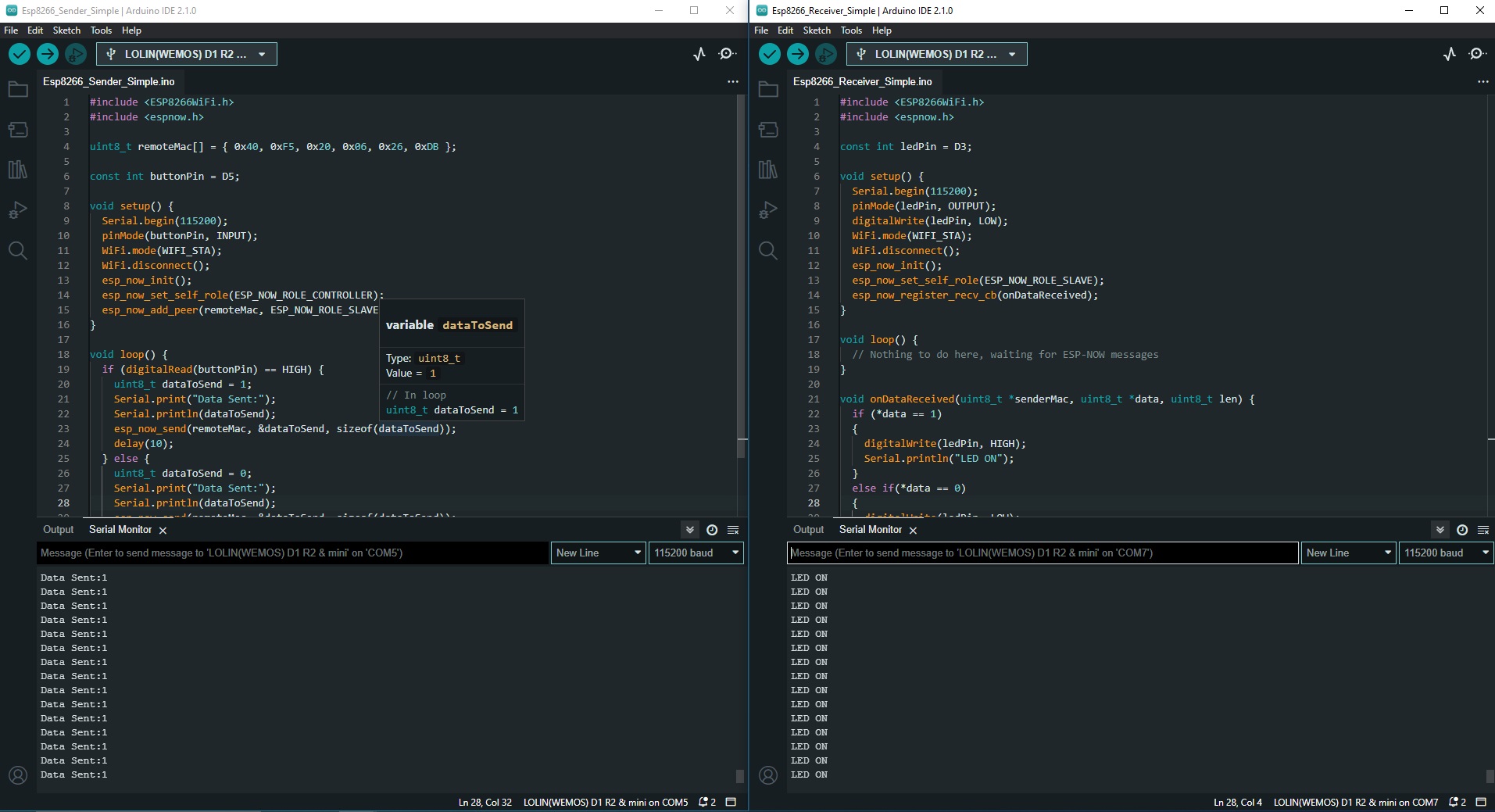
Step 3: Programming the Transmitter
Upload the following code to the transmitter ESP8266:
#include <ESP8266WiFi.h>
#include <espnow.h>

uint8_t remoteMac[] = { 0x40, 0xF5, 0x20, 0x06, 0x26, 0xDB };

const int buttonPin = D5;

void setup() {
  Serial.begin(115200);
  pinMode(buttonPin, INPUT);
  WiFi.mode(WIFI_STA);
  WiFi.disconnect();
  esp_now_init();
  esp_now_set_self_role(ESP_NOW_ROLE_CONTROLLER);
  esp_now_add_peer(remoteMac, ESP_NOW_ROLE_SLAVE, 1, NULL, 0);
}

void loop() {
  if (digitalRead(buttonPin) == HIGH) {
    uint8_t dataToSend = 1;
    Serial.print("Data Sent:");
    Serial.println(dataToSend);
    esp_now_send(remoteMac, &dataToSend, sizeof(dataToSend));
    delay(10);
  } else {
    uint8_t dataToSend = 0;
    Serial.print("Data Sent:");
    Serial.println(dataToSend);
    esp_now_send(remoteMac, &dataToSend, sizeof(dataToSend));
    delay(10);
  }
}
- Replace the receiverMAC variable with the MAC address of your receiver ESP8266.
Code Explained:
- The code first includes the
ESP8266WiFi.handespnow.hlibraries. These libraries are needed for the ESP8266 to communicate using ESP-NOW. - The next line defines the MAC address of the remote device. This is the device that the ESP8266 will send data to.
- The
const int buttonPin = D5;line defines the pin that the button is connected to. In this case, the button is connected to GPIO pin D5. - The
setup()function initializes the serial port, sets the button pin as an input, and configures the ESP8266 to use ESP-NOW. It also sets the ESP8266 as the controller and adds the remote device as a peer. - The
loop()function continuously checks the state of the button. If the button is pressed, the ESP8266 sends a data packet to the remote device. The data packet contains a single byte, which is either 0 or 1, depending on whether the button is pressed or not. - The
esp_now_send()function sends the data packet to the remote device. The first parameter is the MAC address of the remote device, the second parameter is a pointer to the data buffer, and the third parameter is the size of the data buffer. - The
delay()function pauses the execution of the code for a specified number of milliseconds. - In summary, the code uses ESP-NOW to send a data packet to a remote device whenever the button is pressed. The data packet contains a single byte, which is either 0 or 1, depending on whether the button is pressed or not.
Step 4: Programming the Receiver
Upload the following code to the receiver ESP8266:
#include <ESP8266WiFi.h>
#include <espnow.h>

const int ledPin = D3;

void setup() {
  Serial.begin(115200);
  pinMode(ledPin, OUTPUT);
  digitalWrite(ledPin, LOW);
  WiFi.mode(WIFI_STA);
  WiFi.disconnect();
  esp_now_init();
  esp_now_set_self_role(ESP_NOW_ROLE_SLAVE);
  esp_now_register_recv_cb(onDataReceived);
}

void loop() {
  // Nothing to do here, waiting for ESP-NOW messages
}

void onDataReceived(uint8_t *senderMac, uint8_t *data, uint8_t len) {
  if (*data == 1)
  {
    digitalWrite(ledPin, HIGH);
    Serial.println("LED ON");
  }
  else if(*data == 0)
  {
    digitalWrite(ledPin, LOW);
    Serial.println("LED OFF");
}
}
Code Explained:
- The code first includes the
ESP8266WiFi.handespnow.hlibraries. These libraries are needed for the ESP8266 to communicate using ESP-NOW. - The
const int ledPin = D3;line defines the pin that the LED is connected to. In this case, the LED is connected to GPIO pin D3. - The
setup()function initializes the serial port, sets the LED pin as an output, and configures the ESP8266 to use ESP-NOW. It also sets the ESP8266 as the slave and registers a callback function to handle incoming data packets. - The
loop()function does nothing. This is because the ESP8266 is waiting for incoming data packets. - The
onDataReceived()function is the callback function that is called when the ESP8266 receives a data packet. The first parameter is the MAC address of the sender, the second parameter is a pointer to the data buffer, and the third parameter is the size of the data buffer. - The code in the
onDataReceived()function checks the value of the first byte in the data buffer. If the value is 1, the LED is turned on. If the value is 0, the LED is turned off. - In summary, the code uses ESP-NOW to receive data packets from a remote device. The data packets can be used to control the state of the LED.
Step 5: Testing the Connection
- Power both ESP8266 modules.
- Open the Serial Monitor for the transmitter and set the baud rate to 115200.
- Press the button on the transmitter module. The LED on the receiver module should turn on and you would be able to see the data in the Serial Monitor.

Troubleshooting and Tips
- This might be stupid to say, but make sure that you clearly identify the boards as sender and receiver and double-check the port multiple times. This confusion happened to me.
- If you encounter issues with communication, double-check the MAC addresses used in the sender’s code.
- Ensure that both ESP8266 modules are within the range of each other. ESP-NOW typically has a range of about 200 meters in open spaces.
- If you’re using ESP-NOW for battery-powered devices, consider using the
WiFi.setSleepMode()function to save power. - For more advanced use cases, consider using ESP-NOW with encryption enabled for secure communication.
Conclusion
In this tutorial, we demonstrated how to connect two ESP8266 modules using ESP-NOW, with one module controlling an LED on the other module via a button press. This is just the beginning of what you can achieve with ESP-NOW. You can expand this project to control multiple devices or even create a mesh network of ESP8266 modules. Happy experimenting!