Connecting HC-SR501 PIR Sensor to ESP8266
The HC-SR501 PIR (Passive Infrared) Sensor and the ESP8266 are crucial components in many DIY and home automation projects, primarily due to their versatility and ease of use. This blog post will walk you through the process of connecting the HC-SR501 PIR sensor to an ESP8266 without using Wi-Fi, along with a clear explanation of the required code.
Hardware Needed:
- HC-SR501 PIR Sensor (Affiliate) – https://s.click.aliexpress.com/e/_DnS5GIF
- ESP8266 Development Board (such as NodeMCU) (Affiliate) – https://s.click.aliexpress.com/e/_DD3JQhj
- KY-006 Buzzer (Affiliate) – https://s.click.aliexpress.com/e/_DmslOFz
- Breadboard and jumper wires (Affiliate) – https://s.click.aliexpress.com/e/_Dl5kuk1
Goodies:
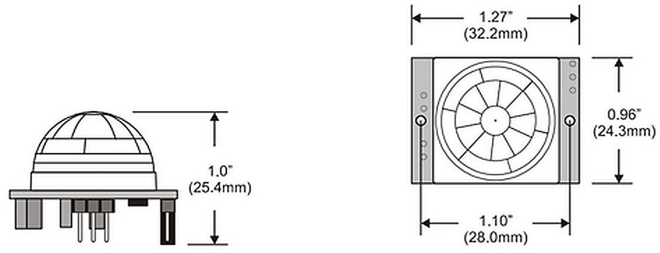
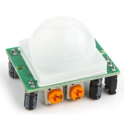
Electronic details:
- This PIR has a range of up to 7 meters, it has 2 adjustment knobs, one for the detection time and one for delay time for the next interval.
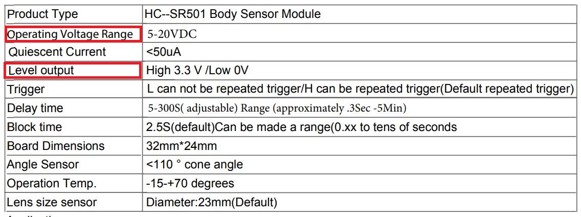
- From the Datasheet we can see that the operating voltage is in the 5 to 20 Volt range. It is better to power the sensor from a regulated external power supply.
- The output voltage will be 3.3 Volt or 0 Volt depending on the level, so that isn´t a problem for the Esp8266. Higher then that, we can say goodbye to the microcontroller like the time that i injected 12v in a pin of an Arduino. The smell wasn´t good…that is the only thing i can say.
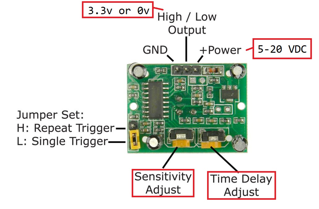
We can also adjust the Sensitivity and the Time Delay (From the datasheet):
- Adjust the distance potentiometer clockwise rotation, increased sensing distance (about 7 meters), on the contrary, the sensing distance
decreases (about 3 meters). - Adjust the delay potentiometer clockwise rotation sensor the delay lengthened (300S), on the contrary, shorten the induction delay (5S).
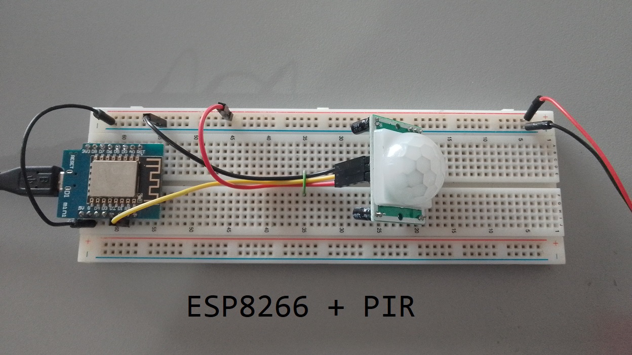
Setting Up The Circuit:
- Connect the VCC pin of the PIR sensor to the +5V/+12V pin to a External Regulated Power Source for the sensor to behave correctly (Or from the 5V pin of the Esp8266 but i don´t recommend it).
- Connect the GND pin of the PIR sensor to the GND pin of the ESP8266.
- Finally, connect the OUT pin of the PIR sensor to a digital pin on the ESP8266, for example, D1.

Understanding the Code:
Now that the hardware setup is ready, let’s decipher the code to acquire data from the PIR sensor and interpret it via the ESP8266.
- Define the digital pin connected to the OUT pin of the PIR sensor:
const int pirPin = D1; // D1 is just an example, you can connect it to the pin of your choice
- Initialize the PIR sensor pin as INPUT in the setup method:
void setup() {
pinMode(pirPin, INPUT);
Serial.begin(115200); // Set baud rate for serial communication
}
- In the loop method, read the sensor output and print a corresponding message:
void loop() {
int motionDetected = digitalRead(pirPin);
if (motionDetected == HIGH) {
Serial.println("Motion Detected!");
} else {
Serial.println("No Motion Detected.");
}
delay(1000); // Delay for 1 second for easy reading
}
Code explanation:
This simple yet effective code commences with defining the pin to which the PIR sensor is connected. In our case, it’s pin D1. In the ‘setup’ function, this pin is declared as ‘INPUT’, which allows the ESP8266 to read data from the PIR sensor. Also, the baud rate for serial communication is set at 115200.
The ‘loop’ function perpetually checks for any movements detected by the sensor and fetches the sensor’s output through the ‘digitalRead’ function. If movement is detected (HIGH), a corresponding message is printed on the serial monitor. If no movement is detected (LOW), it prints a different message. A delay of 1 second is added for comfortable reading on the serial monitor.
Complete Code
const int pirPin = D1;  // D1 is just an example, you can connect it to the pin of your choice

void setup() {
  pinMode(pirPin, INPUT);
  Serial.begin(115200);  // Set baud rate for serial communication
}

void loop() {
  int motionDetected = digitalRead(pirPin);
  if (motionDetected == HIGH) Serial.println("Motion Detected!");
  else Serial.println("No Motion Detected.");
  delay(1000);  // Delay for 1 second for easy reading
}

Connecting HC-SR501 PIR Sensor and Buzzer to ESP8266
We will take your HC-SR501 PIR sensor and ESP8266 project to the next level by adding a buzzer to create an audible alert when motion is detected. We’ll cover the necessary wiring connections and provide a comprehensive explanation of the code required to implement the buzzer functionality.
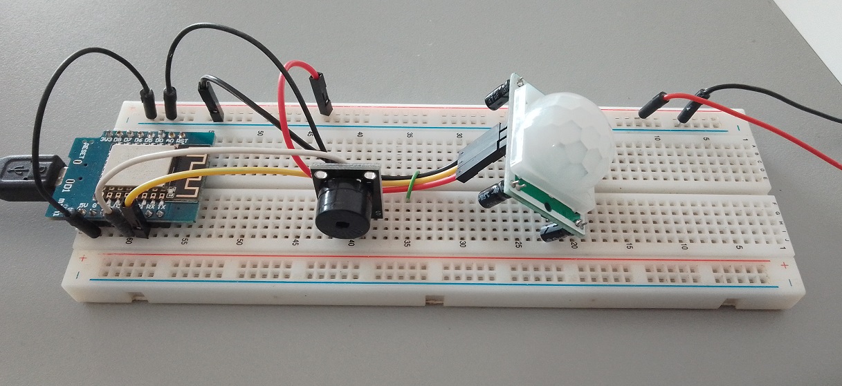
Circuit Connections:
- Connect the VCC pin of the PIR sensor to the +12V pin to a External Regulated Power Source for the sensor to behave correctly.
- Connect the GND pin of the PIR sensor to the GND pin of the ESP8266.
- Finally, connect the OUT pin of the PIR sensor to a digital pin on the ESP8266, for example, D1.
- Connect the positive terminal of the buzzer to a digital pin of the ESP8266, for example, D2.
- Connect the negative terminal of the buzzer to the GND pin of the ESP8266/Global.

Code Explanation:
Now, let’s dive into the code required to integrate the buzzer with the HC-SR501 PIR sensor and ESP8266.
- Define the pin connections:
const int pirPin = D1;     // PIR sensor pin
const int buzzerPin = D2;  // Buzzer pin
- Set up the initial configurations:
void setup() {
  pinMode(pirPin, INPUT);
  pinMode(buzzerPin, OUTPUT);
  Serial.begin(115200);
}
- Implement the logic to detect motion and trigger the buzzer:
void loop() {
  int motionDetected = digitalRead(pirPin);
  if (motionDetected == HIGH) {
    Serial.println("Motion Detected!");
    for (int i = 0; i < 100; i++) {  // make a sound
        digitalWrite(buzzerPin, HIGH); // send high signal to buzzer
        delay(1); // delay 1ms
        digitalWrite(buzzerPin, LOW); // send low signal to buzzer
        delay(1);
    }
    delay(50);
    for (int j = 0; j < 100; j++) { //make another sound
        digitalWrite(buzzerPin, HIGH);
        delay(2); // delay 2ms
        digitalWrite(buzzerPin, LOW);
        delay(2);
    }
    delay(500);
  } else {
    Serial.println("No Motion Detected.");
  }
  delay(1000);  // Delay between readings
}
Complete code:
const int pirPin = D1;     // PIR sensor pin
const int buzzerPin = D2;  // Buzzer pin

void setup() {
  pinMode(pirPin, INPUT);
  pinMode(buzzerPin, OUTPUT);
  Serial.begin(115200);
}

void loop() {
  int motionDetected = digitalRead(pirPin);
  if (motionDetected == HIGH) {
    Serial.println("Motion Detected!");
    for (int i = 0; i < 100; i++) {  // make a sound
        digitalWrite(buzzerPin, HIGH); // send high signal to buzzer
        delay(1); // delay 1ms
        digitalWrite(buzzerPin, LOW); // send low signal to buzzer
        delay(1);
    }
    delay(50);
    for (int j = 0; j < 100; j++) { //make another sound
        digitalWrite(buzzerPin, HIGH);
        delay(2); // delay 2ms
        digitalWrite(buzzerPin, LOW);
        delay(2);
    }
    delay(500);
  } else {
    Serial.println("No Motion Detected.");
  }
  delay(1000);  // Delay between readings
}
Video
Conclusion:
Connecting an HC-SR501 PIR sensor to an ESP8266 and interpreting the data has now been streamlined for you! With a simple setup and easy-to-understand piece of code, you are ready to implement this in any of your projects requiring motion detection. Have incredible fun experimenting and building!