
Connecting an ESP8266 to a Rotary Encoder
In this blog post, we will explore how to connect a WeMos D1 Mini (ESP8266 Arduino platform) to a KY-040 rotary encoder. Rotary encoders are versatile input devices that can be used in various applications, such as adjusting settings, navigating menus, or controlling volume. We will discuss the necessary hardware connections, provide a sample code, and explain how to debounce the encoder for accurate readings.
Components Required
- ESP8266 development board (e.g., NodeMCU or Wemos D1 Mini) (Affiliate) – https://s.click.aliexpress.com/e/_DD3JQhj
- KY-040 Rotary Encoder – (Affiliate) – https://s.click.aliexpress.com/e/_De383g3
- Breadboard and jumper wires (Affiliate) – https://s.click.aliexpress.com/e/_Dl5kuk1
Hardware Connections:
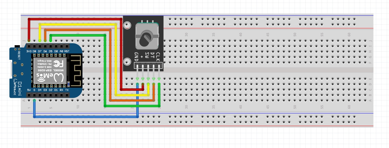
To connect the WeMos D1 Mini to the KY-040 rotary encoder, follow these steps:
- Connect the VCC pin of the KY-040 to the 3.3V pin on the WeMos D1 Mini.
- Connect the GND pin of the KY-040 to the GND pin on the WeMos D1 Mini.
- Connect the CLK pin of the KY-040 to the D5 pin on the WeMos D1 Mini.
- Connect the DT pin of the KY-040 to the D6 pin on the WeMos D1 Mini.
- Connect the SW pin of the KY-040 to the D7 pin on the WeMos D1 Mini if you want to use the built-in push button of the rotary encoder.
Sample Code
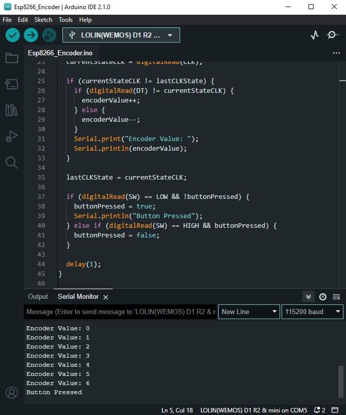
Here’s a sample code to read the rotary encoder values using the WeMos D1 Mini:
const int CLK = D5;
const int DT = D6;
const int SW = D7;

int encoderValue = 0;
int lastCLKState;
int currentStateCLK;
bool buttonPressed = false;


void setup() {
  pinMode(CLK, INPUT);
  pinMode(DT, INPUT);
  pinMode(SW, INPUT_PULLUP);

  lastCLKState = digitalRead(CLK);

  Serial.begin(115200);
}

void loop() {
  currentStateCLK = digitalRead(CLK);

  if (currentStateCLK != lastCLKState) {
    if (digitalRead(DT) != currentStateCLK) {
      encoderValue++;
    } else {
      encoderValue--;
    }
    Serial.print("Encoder Value: ");
    Serial.println(encoderValue);
  }

  lastCLKState = currentStateCLK;

  if (digitalRead(SW) == LOW && !buttonPressed) {
    buttonPressed = true;
    Serial.println("Button Pressed");
  } else if (digitalRead(SW) == HIGH && buttonPressed) {
    buttonPressed = false;
  }

  delay(1);
}
Expanding the code
The provided code is written for Arduino and is used to read the values from a rotary encoder. A rotary encoder is a type of position sensor which is commonly used for determining the angle of rotation. This specific rotary encoder also has a push button incorporated into it. Here’s a breakdown of the code:
These lines define the pins to which the three wires from the rotary encoder are connected. CLK and DT are the two pins used to read the rotation. SW is the pin used to read the push button.
const int CLK = D5;
const int DT = D6;
const int SW = D7;
encoderValue is the variable that keeps track of the current position of the rotary encoder. lastCLKState and currentStateCLK are used to compare the previous and current state of the CLK pin to determine the direction of rotation. buttonPressed is a boolean variable used to track the state of the push button.
int encoderValue = 0;
int lastCLKState;
int currentStateCLK;
bool buttonPressed = false;
The setup() function initializes the pins as input and starts serial communication at a baud rate of 115200 for debugging purposes. The initial state of the CLK pin is also read into lastCLKState.
void setup() {
  pinMode(CLK, INPUT);
  pinMode(DT, INPUT);
  pinMode(SW, INPUT_PULLUP);

  lastCLKState = digitalRead(CLK);

  Serial.begin(115200);
}
This part of the loop() function reads the current state of the CLK pin and compares it with the last state. Depending on the states of CLK and DT, it increments or decrements encoderValue. The updated encoder value is then printed to the serial monitor.
void loop() {
  currentStateCLK = digitalRead(CLK);
  if (currentStateCLK != lastCLKState) {
    if (digitalRead(DT) != currentStateCLK) {
      encoderValue++;
    } else {
      encoderValue--;
    }
    Serial.print("Encoder Value: ");
    Serial.println(encoderValue);
  }

  lastCLKState = currentStateCLK;
The final part of the loop() function reads the state of the push button. If the button is pressed (SW reads LOW), it prints “Button Pressed” to the serial monitor. The buttonPressed boolean is used to prevent the message from being printed continuously while the button is held down. The delay(1) line is used to debounce the inputs.
if (digitalRead(SW) == LOW && !buttonPressed) {
    buttonPressed = true;
    Serial.println("Button Pressed");
  } else if (digitalRead(SW) == HIGH && buttonPressed) {
    buttonPressed = false;
  }

  delay(1);
}
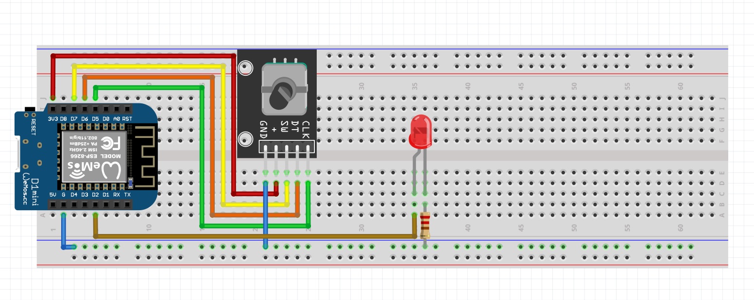
Hardware Connections:
- Connect the anode (longer leg) of the LED to the D2 pin on the WeMos D1 Mini.
- Connect the cathode (shorter leg) of the LED to a 220-ohm resistor.
- Connect the other end of the resistor to the GND pin on the WeMos D1 Mini.
Sample Code
const int CLK = D5;
const int DT = D6;
const int SW = D7;
const int LED_PIN = D2;

int encoderValue = 0;
int lastCLKState;
int currentStateCLK;
bool buttonPressed = false;
int ledBrightness = 0;

void setup() {
  pinMode(CLK, INPUT);
  pinMode(DT, INPUT);
  pinMode(SW, INPUT_PULLUP);
  pinMode(LED_PIN, OUTPUT);

  lastCLKState = digitalRead(CLK);

  Serial.begin(115200);
}

void loop() {
  currentStateCLK = digitalRead(CLK);

  if (currentStateCLK != lastCLKState) {
    if (digitalRead(DT) != currentStateCLK) {
      encoderValue++;
    } else {
      encoderValue--;
    }
    Serial.print("Encoder Value: ");
    Serial.println(encoderValue);
  }

  // Map the counter value to LED brightness (0-255)
  ledBrightness = map(encoderValue, 0, 100, 0, 255);
  ledBrightness = constrain(ledBrightness, 0, 255);
  analogWrite(LED_PIN, ledBrightness);

  lastCLKState = currentStateCLK;

  if (digitalRead(SW) == LOW && !buttonPressed) {
    buttonPressed = true;
    Serial.println("Button Pressed");

    encoderValue=0;
    analogWrite(LED_PIN, encoderValue);

  } else if (digitalRead(SW) == HIGH && buttonPressed) {
    buttonPressed = false;
  }

  delay(1);
}
Conclusion