
Connecting a OLED Display to Wemos D1 Mini
The OLED Display
An OLED is a type of LED where the emissive electroluminescent layer is made of organic compounds. Unlike traditional LEDs, OLEDs don’t require a backlight. Instead, each individual pixel emits its own light when an electric current is applied. This allows OLED displays to be thinner, more flexible, and offer better contrast ratios compared to some other display technologies.

Technical Specifications
- OLED Technology, Self-luminous, need no back-light (consumes less energy)
- High resolution: 128 * 64
- Viewing angle:> 160 degree
- Supports various microcontrollers: Fully compatible with Raspberry Pi, Arduino, 51 Series, MSP430 Series, STM32 / 2, CSR IC, etc.
- Ultra-low power consumption: full screen lit 0.08W
- Operating Voltage: 3.3V Nominal (3.3-6V)
- Compatible I/O level: 3.3V / 5V
- Working Temperature: :-30 ~70 Celsius
- Driver IC: SSD1306


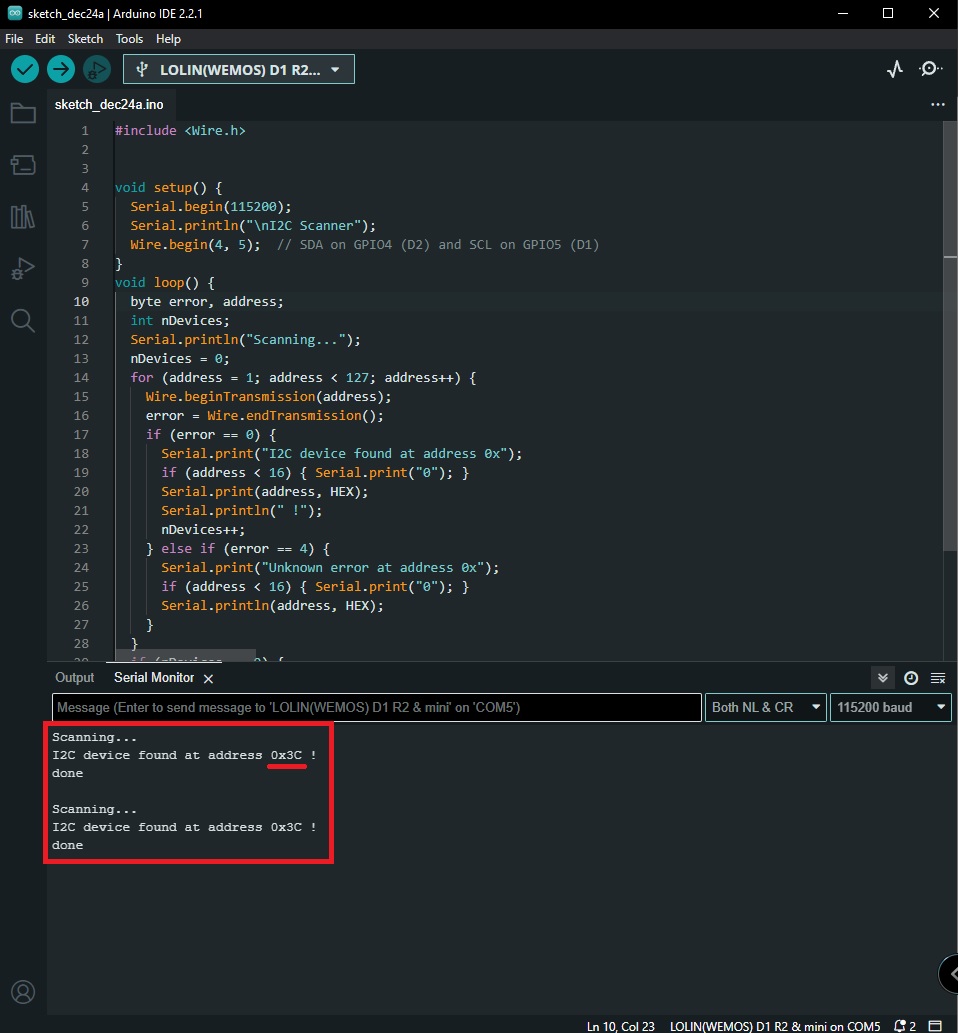
Testing I2C Communication with Wemos D1 Mini
Before diving into the OLED display project, it’s essential to ensure that the Wemos D1 Mini can communicate with the OLED display through the I2C protocol. The provided code is an I2C scanner that identifies devices on the I2C bus and their addresses.
I2C Scanner Code
#include <Wire.h>

void setup() {
  Serial.begin(115200);
  Serial.println("\nI2C Scanner");
  Wire.begin(4, 5); // SDA on GPIO4 (D2) and SCL on GPIO5 (D1)
}

void loop() {
  byte error, address;
  int nDevices;

  Serial.println("Scanning...");

  nDevices = 0;
  for (address = 1; address < 127; address++) {
    Wire.beginTransmission(address);
    error = Wire.endTransmission();

    if (error == 0) {
      Serial.print("I2C device found at address 0x");
      if (address < 16) {
        Serial.print("0");
      }
      Serial.print(address, HEX);
      Serial.println(" !");

      nDevices++;
    } else if (error == 4) {
      Serial.print("Unknown error at address 0x");
      if (address < 16) {
        Serial.print("0");
      }
      Serial.println(address, HEX);
    }
  }
  if (nDevices == 0) {
    Serial.println("No I2C devices found\n");
  } else {
    Serial.println("done\n");
  }
  delay(2000);
}
Code Explanation:
- Library Inclusion:
#include <Wire.h>includes the Wire library, which is essential for I2C communication.
- Setup Function:
Serial.begin(115200)initializes serial communication for debugging purposes.Wire.begin(4, 5)initializes the I2C communication with SDA on GPIO4 (D2) and SCL on GPIO5 (D1) of the Wemos D1 Mini.
- Loop Function:
for (address = 1; address < 127; address++): Iterates through possible I2C addresses (from 1 to 126).Wire.beginTransmission(address): Begins transmission to the specified I2C address.error = Wire.endTransmission(): Ends transmission and checks for errors.
- Checking Errors:
- If
error == 0, the I2C device is found at the given address. It prints the address in hexadecimal format. - If
error == 4, an unknown error occurred at the address.
- If
- Displaying Results:
- It keeps track of the number of devices found (
nDevices) and displays the results.
- It keeps track of the number of devices found (
- Delay:
delay(2000): Delays the scanning process for 5 seconds before repeating.
Running the I2C Scanner:
- Connect the Wemos D1 Mini to your computer.
- Upload the I2C Scanner code to the Wemos D1 Mini.
- Open the Serial Monitor in the Arduino IDE (
Tools > Serial Monitor). - Observe the output, which will display any I2C devices found and their addresses.

Understanding the Code
Let’s break down the provided Arduino code to understand how it interacts with the OLED display and the Wemos D1 Mini.
#include <Wire.h>
#include <U8g2lib.h>

#define SCREEN_WIDTH 128
#define SCREEN_HEIGHT 64
#define I2C_ADDRESS   0x3C  // Replace with the correct I2C address

U8G2_SSD1306_128X64_NONAME_F_HW_I2C u8g2(U8G2_R0, /* reset=*/ U8X8_PIN_NONE);
- The
#includestatements include necessary libraries.Wire.his used for I2C communication, andU8g2lib.his the graphics library for the OLED display. SCREEN_WIDTHandSCREEN_HEIGHTdefine the dimensions of the OLED display.I2C_ADDRESSspecifies the I2C address of the OLED display. Replace it with the correct address if it differs from the default.- The
U8G2_SSD1306_128X64_NONAME_F_HW_I2Cline initializes theU8g2object with the display type, rotation (U8G2_R0means no rotation), and hardware I2C.U8X8_PIN_NONEis used for the reset pin.
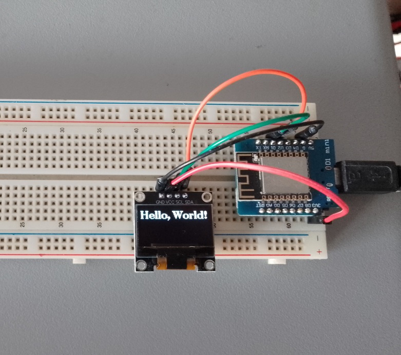
void setup() {
  Serial.begin(115200);

  u8g2.begin();
  u8g2.clearBuffer();

  u8g2.setFont(u8g2_font_ncenB14_tr);  // Set font
  u8g2.drawStr(0, 20, "Hello, World!");  // Draw the string
  u8g2.sendBuffer();  // Send the buffer to the display
}
Serial.begin(115200)initializes the serial communication for debugging purposes.u8g2.begin()initializes the U8g2 library.u8g2.clearBuffer()clears the display buffer.u8g2.setFont(u8g2_font_ncenB14_tr)sets the font to a 14-point bold font.u8g2.drawStr(0, 20, "Hello, World!")draws the string “Hello, World!” at coordinates (0, 20) on the display.u8g2.sendBuffer()sends the buffer to the OLED display, making the drawn text visible.
void loop() {
  // Nothing to loop here
}
The loop() function is empty because the display is set up in the setup() function, and there’s no need for continuous looping in this simple example.
Feel free to modify the code to display different text or graphics, experiment with fonts, and explore additional features provided by the U8g2 library to enhance your OLED display projects.
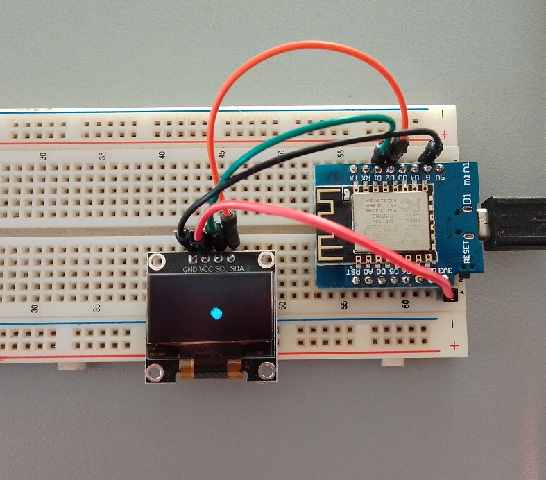
Bouncing Ball Animation Example
Here’s an example of a bouncing ball animation using the U8g2 library on an OLED display with the Wemos D1 Mini:
#include <Wire.h>
#include <U8g2lib.h>

#define SCREEN_WIDTH 128
#define SCREEN_HEIGHT 64
#define I2C_ADDRESS   0x3C  // Replace with the correct I2C address

U8G2_SSD1306_128X64_NONAME_F_HW_I2C u8g2(U8G2_R0, /* reset=*/ U8X8_PIN_NONE);

int ballX = 10;  // Initial X-coordinate of the ball
int ballY = 10;  // Initial Y-coordinate of the ball
int ballSpeedX = 2;  // Speed of the ball in the X direction
int ballSpeedY = 2;  // Speed of the ball in the Y direction

void setup() {
  Serial.begin(115200);

  u8g2.begin();
}

void loop() {
  u8g2.clearBuffer();

  // Draw the bouncing ball
  u8g2.drawDisc(ballX, ballY, 5);  // Draw a filled circle as the ball

  // Update the ball's position
  ballX += ballSpeedX;
  ballY += ballSpeedY;

  // Bounce the ball when it reaches the screen edges
  if (ballX <= 5 || ballX >= SCREEN_WIDTH - 5) {
    ballSpeedX = -ballSpeedX;
  }

  if (ballY <= 5 || ballY >= SCREEN_HEIGHT - 5) {
    ballSpeedY = -ballSpeedY;
  }

  u8g2.sendBuffer();  // Send the buffer to the display
  delay(30);  // Adjust the delay to control the animation speed
}
In this example, a filled circle is drawn as the bouncing ball. The ball starts at coordinates (10, 10) and moves with a speed of 2 pixels per frame in both the X and Y directions. When the ball reaches the screen edges, it bounces back. The delay(30) controls the speed of the animation; you can adjust it to make the animation faster or slower.
Complex Animation Example
To create a more complex animation with a star shape, we can modify the code to use a series of lines to draw the star.
#include <Wire.h>
#include <U8g2lib.h>

#define SCREEN_WIDTH 128
#define SCREEN_HEIGHT 64
#define I2C_ADDRESS   0x3C  // Replace with the correct I2C address

U8G2_SSD1306_128X64_NONAME_F_HW_I2C u8g2(U8G2_R0, /* reset=*/ U8X8_PIN_NONE);

float angle = 0.0;  // Initial angle for rotation
float scale = 1.0;  // Initial scale factor
int color = 0;      // Initial color index

void setup() {
  Serial.begin(115200);

  u8g2.begin();
}

void loop() {
  u8g2.clearBuffer();

  // Calculate the coordinates for the star based on the angle and scale
  int x[5], y[5];
  for (int i = 0; i < 5; i++) {
    float theta = angle + i * 2 * PI / 5;
    x[i] = SCREEN_WIDTH / 2 + scale * 20 * cos(theta);
    y[i] = SCREEN_HEIGHT / 2 + scale * 20 * sin(theta);
  }

  // Draw the star using lines
  for (int i = 0; i < 5; i++) {
    int nextIndex = (i + 2) % 5;
    u8g2.drawLine(x[i], y[i], x[nextIndex], y[nextIndex]);
  }

  // Update animation parameters
  angle += 0.05;
  scale = 1.0 + 0.5 * sin(angle * 2);  // Scale changes dynamically
  color = (color + 1) % 2;              // Alternating between two colors

  // Set color based on the current color index
  if (color == 0) {
    u8g2.setDrawColor(1);  // White
  } else {
    u8g2.setDrawColor(0);  // Black
  }

  u8g2.sendBuffer();  // Send the buffer to the display

  // Adjust the delay to control the animation speed
  delay(30);
}
This example uses the drawLine method to draw the lines connecting the points of the star.

Frequently Asked Questions (FAQ)
1. What do I do if the I2C scanner doesn’t find any devices?
- Double-check your wiring to ensure proper connections between the Wemos D1 Mini, OLED display, and the breadboard.
- Confirm that the OLED display is powered and functioning.
- Ensure that the I2C address in the OLED display code matches the address used in the I2C scanner code.
2. How can I troubleshoot if the OLED display doesn’t show the “Hello, World!” message?
- Confirm that the Wemos D1 Mini is correctly connected to the OLED display.
- Check the power supply to the OLED display and ensure it’s receiving power.
- Verify that the I2C address in the OLED display code matches the actual address of the connected display.
3. Can I use a different font for the text on the OLED display?
- Yes, the U8g2 library supports various fonts. You can explore and choose a different font by modifying the
u8g2.setFont()line in the OLED display code.
4. What if I want to display more complex graphics on the OLED screen?
- The U8g2 library provides extensive features for graphics. Explore the library documentation to learn how to draw lines, circles, rectangles, and even custom graphics on the OLED display.
5. How can I modify the code to display dynamic information instead of a static message?
- You can update the
loop()function to include dynamic content. For example, you could read sensor data or display real-time information retrieved from the internet.
6. Why is the delay of 2 seconds included in the I2C scanner code?
- The delay is added to give you time to observe the I2C scanner output in the Serial Monitor. It waits for 2 seconds before repeating the scanning process.
7. What should I do if I encounter errors during code upload or execution?
- Check the Arduino IDE for error messages during code upload. Ensure that the correct board and COM port are selected.
- Examine the Serial Monitor for runtime errors and address any issues based on the error messages.
8. Can I use a different ESP8266-based board instead of the Wemos D1 Mini?
- Yes, you can adapt the code for other ESP8266 boards by adjusting pin configurations and ensuring compatibility with the U8g2 library.
9. Where can I find more information about the U8g2 library?
- Visit the official U8g2 library documentation on GitHub for detailed information about the library’s features and usage: U8g2 Library GitHub.
10. What are some potential projects I can create with Wemos D1 Mini and an OLED display?
- Explore projects like weather stations, IoT devices, fitness trackers, or any application that benefits from a compact display for information output.