
Connect ESP01 to an OLED Display
In this tutorial, we will explore how to connect an ESP01 (ESP8266) microcontroller to an OLED display using the U8g2lib library. OLED displays are compact, lightweight, and offer excellent visibility, making them perfect for various projects where real-time data display is required. By following this guide, you’ll be able to harness the power of ESP01 and visualize data on an OLED display effortlessly.
Requirements:
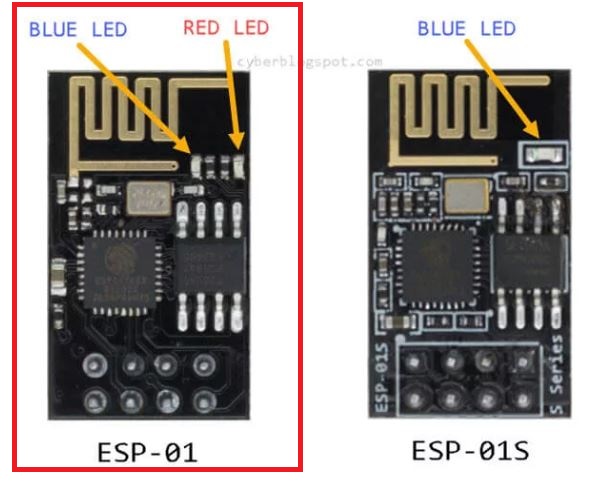
- ESP-01 Wi-Fi module (Affiliate) – https://s.click.aliexpress.com/e/_DETsfWR
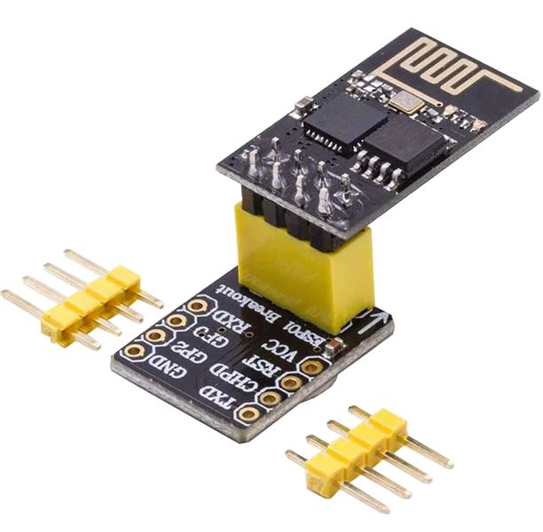
- Breadboard adapter for ESP-01 (Affiliate) – https://s.click.aliexpress.com/e/_DC3gXdN
- Breadboard and jumper wires (Affiliate) – https://s.click.aliexpress.com/e/_Dl5kuk1
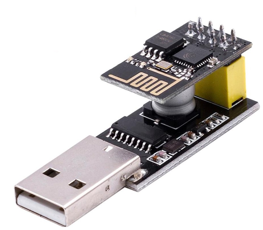
- USB ESP-01 Programming Adapter with a CH340G chip (Affiliate) – https://s.click.aliexpress.com/e/_DETsfWR
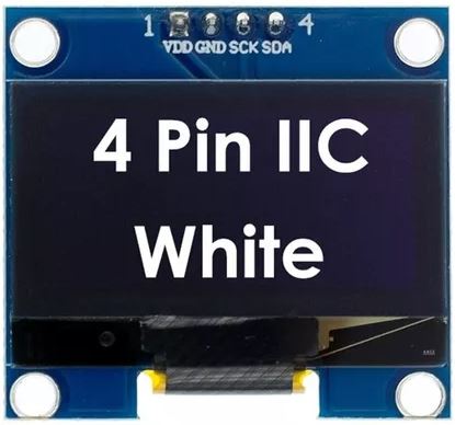
- OLED Display (128×64 pixels) (Affiliate) – https://s.click.aliexpress.com/e/_Dm4UE3J
- Arduino IDE or any other ESP8266 compatible programming environment
Setting Up the Libraries

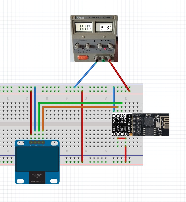
Wiring the Components
Connect the ESP01 and OLED display as follows:
Writing the Main Code
Now, let’s write the main code to display information on the OLED display. Copy and paste the following code into your Arduino IDE:
#include <Wire.h>
#include <U8g2lib.h>

#define SCREEN_WIDTH 128
#define SCREEN_HEIGHT 64
#define I2C_ADDRESS   0x3C  // Replace with the correct I2C address

U8G2_SSD1306_128X64_NONAME_F_HW_I2C u8g2(U8G2_R0, /* reset=*/ U8X8_PIN_NONE, /* clock=*/ 0, /* data=*/ 2); // GPIO0 for SCL, GPIO2 for SDA

void setup() {
  Serial.begin(115200);

  Wire.begin(0, 2); // GPIO0 for SCL, GPIO2 for SDA
  u8g2.begin();
  u8g2.clearBuffer();

  u8g2.setFont(u8g2_font_ncenB14_tr);  // Set font
  u8g2.drawStr(0, 20, "Hello, World!");  // Draw the string
  u8g2.sendBuffer();  // Send the buffer to the display
}

void loop() {
  // Nothing to loop here
}
This code initializes the OLED display, clears any existing content, sets text color and size, displays “Hello, World!” on the screen, and continuously loops, though it’s empty since there’s no need for any other actions in this example.
Code Explained
This code is designed to work with an ESP8266 module (ESP-01) and an OLED display, utilizing the U8g2lib library for driving the display. Let’s break down the code step by step:
- Include Libraries:
#include <Wire.h>
#include <U8g2lib.h>
These lines include the necessary libraries for I2C communication (Wire.h) and for interfacing with the OLED display (U8g2lib.h).
- Define Constants:
#define SCREEN_WIDTH 128
#define SCREEN_HEIGHT 64
#define I2C_ADDRESS   0x3C  // Replace with the correct I2C address
- Instantiate Display Object:
U8G2_SSD1306_128X64_NONAME_F_HW_I2C u8g2(U8G2_R0, /* reset=*/ U8X8_PIN_NONE, /* clock=*/ 0, /* data=*/ 2);
An object u8g2 of type U8G2_SSD1306_128X64_NONAME_F_HW_I2C is created. This represents the OLED display. The parameters passed to the constructor specify the display type and the hardware I2C pins to use (GPIO0 for SCL and GPIO2 for SDA).
- Setup Function:
void setup() {
  Serial.begin(115200);

  Wire.begin(0, 2); // GPIO0 for SCL, GPIO2 for SDA
  u8g2.begin();
  u8g2.clearBuffer();

  u8g2.setFont(u8g2_font_ncenB14_tr);  // Set font
  u8g2.drawStr(0, 20, "Hello, World!");  // Draw the string
  u8g2.sendBuffer();  // Send the buffer to the display
}
-
- The
setup()function initializes the serial communication at a baud rate of 115200. - It initializes the I2C communication using the specified pins.
- The display is initialized using
u8g2.begin(). - The display buffer is cleared.
- A font is set using
u8g2.setFont()(a built-in fontu8g2_font_ncenB14_tris used). - The string “Hello, World!” is drawn at coordinates (0, 20) on the display.
- Finally, the buffer is sent to the display using
u8g2.sendBuffer().
- The
- Loop Function:
void loop() {
  // Nothing to loop here
}
Since there’s nothing to continuously update or check in this example, the loop() function remains empty.
In summary, this code initializes an OLED display, clears its buffer, writes “Hello, World!” on it, and sends the updated buffer to the display. This setup is executed once in the setup() function, and there’s no continuous processing required, hence the empty loop() function.
Connecting the USB to TTL Converter
To put the CH340G adapter in programming mode, follow these steps:
- Before plugging the USB ESP-01 programming adapter into a USB port on your computer, Press and hold the push button switch that you soldered in Step 2 for a few seconds.
- Plug the USB ESP-01 programming adapter into a USB port on your computer with the button pressed.
- Release the button: After a few seconds, release the push button switch. The Esp-01 should be in programming mode, and you can upload code to the ESP-01 module using your preferred development environment.
If having trouble, go to my previous blog post. It explains with images: https://www.edgemicrotech.com/preparing-the-usb-esp-01-programming-adapter-a-step-by-step-guide/
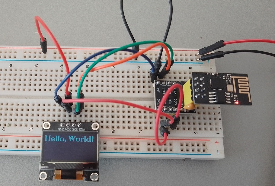
Uploading the Code and Result
Connect your ESP01 to your computer via USB, select the correct board and port in the Arduino IDE, then click the upload button.
In summary, this code initializes an OLED display and writes “Hello, World!”
Conclusion
By following this tutorial, you’ve successfully connected an ESP01 microcontroller to an OLED display using the U8g2lib library. Before using the main code, it’s important to verify the I2C address of your OLED display. This setup opens up a world of possibilities for projects requiring real-time data visualization. Experiment with different data sources and display formats to create engaging and informative displays for your projects.